


1 - 37
1 OVERVIEW
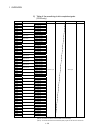
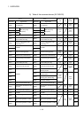
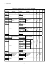
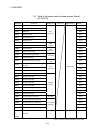
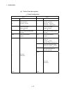
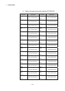
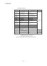
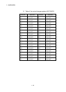
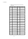
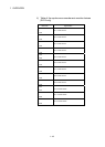
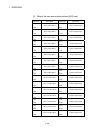
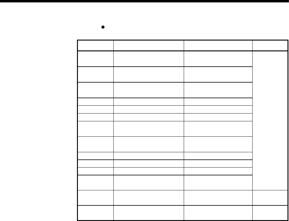
Detailes of each axis
Device No. SV13/SV22(Real mode) SV22(Virtual mode) Signal derection
D0 + 20n
D1 + 20n
Feed current value
Feed current value/roller cycle
speed
D2 + 20n
D3 + 20n
Real current value Real current value
D4 + 20n
D5 + 20n
Deviation counter value Deviation counter value
D6 + 20n Minor error code Minor error code
D7 + 20n Major error code Major error code
D8 + 20n Servo error code Servo error code
D9 + 20n
Home position return re-travel
value
Hold
D10 + 20n
D11 + 20n
Travel value after proximity dog
ON
Hold
D12 + 20n Execute program No. —
D13 + 20n M-code —
D14 + 20n Torque limit value Torque limit value
D15 + 20n
Data set pointer for constant-
speed control
—
Monitor device
D16 + 20n
D17 + 20n
Travel value change register —
Command
device
D18 + 20n
D19 + 20n
Real current value at stop input Hold Monitor device
(Note-1) : "n" in the above device No. shows the numerical value which correspond to axis No.
Q173CPU(N) : Axis No.1 to No.32 (n=0 to 31)
Q172CPU(N) : Axis No.1 to No.8 (n=0 to 7)
(Note-2) : Device area of 9 axes or more is unusable in the Q172CPU(N).