3 - 14
3 COMMUNICATION BETWEEN THE PLC CPU AND THE MOTION CPU IN
THE MULTIPLE CPU SYSTEM
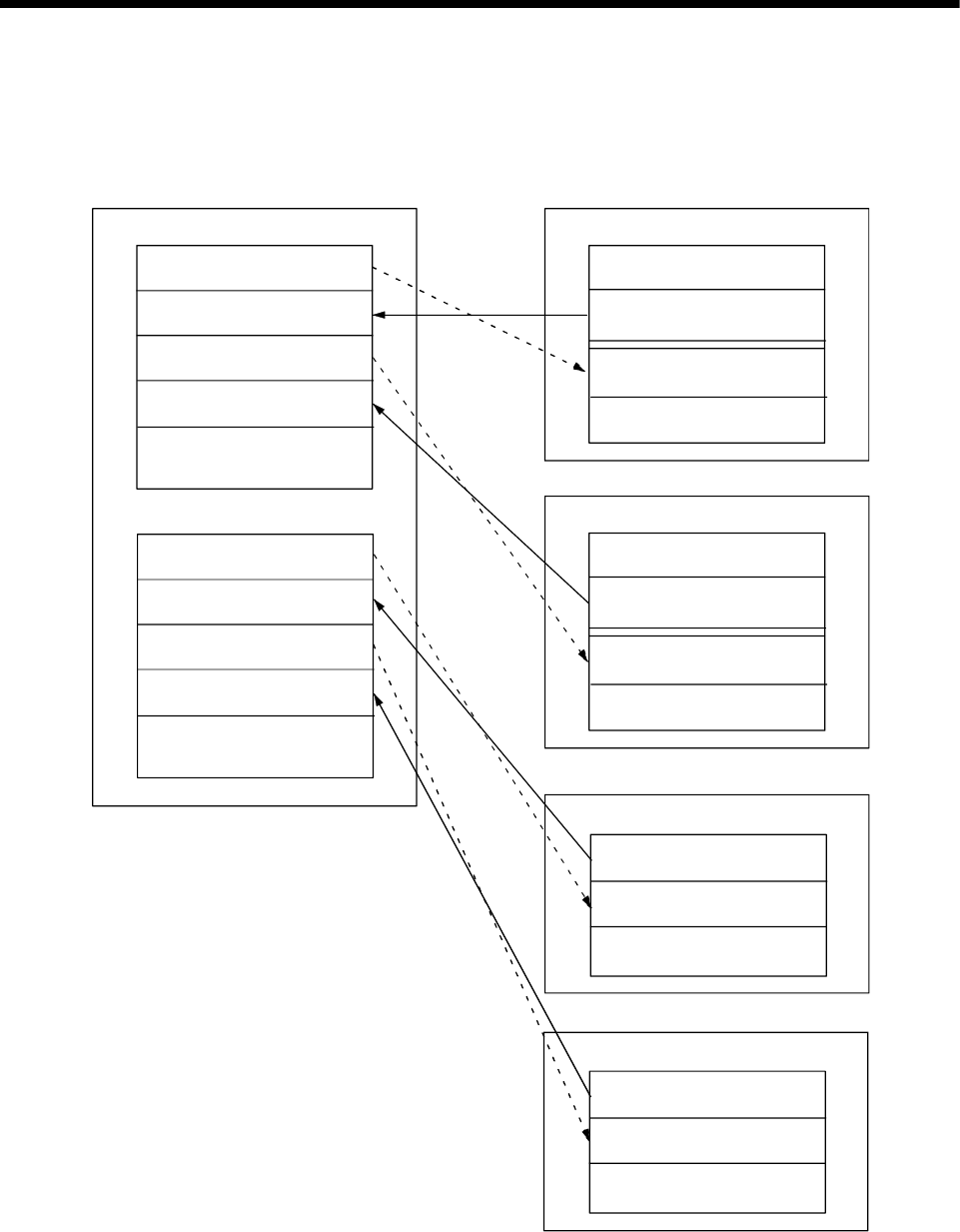
2) PLC CPU (1 module) + Motion CPU (2 modules)
The outline operation and the automatic refresh setting are shown
below.
Command device for
the Motion CPU No.2
(768 points)
CPU No.1 (PLC CPU)
Data registers
CPU No.2 (Motion CPU)
M0
M768
M1824
M2592
M3648
M8191
Monitor device for
the Motion CPU No.2
(1056 points)
Internal relays
M0
M2000
M3055
M3072
M3839
M3840
M8191
Monitor device
(1056 points)
Command device
(768 points)
Internal relays
Command device for
the Motion CPU No.3
(768 points)
Monitor device for
the Motion CPU No.3
(1056 points)
Command device for
the Motion CPU No.2
(118 points)
D0
D118
D758
D876
D1516
D8191
Monitor device for
the Motion CPU No.2
(640 points)
Command device for
the Motion CPU No.3
(118 points)
Monitor device for
the Motion CPU No.3
(640 points)
CPU No.2 (Motion CPU)
Data registers
D0
D640
D758
D8191
Monitor device
(640 points)
Command device
(118 points)
CPU No.3 (Motion CPU)
M0
M2000
M3055
M3072
M3839
M3840
M8191
Monitor device
(1056 points)
Command device
(768 points)
Internal relays
CPU No.3 (Motion CPU)
Data registers
D0
D640
D758
D8191
Monitor device
(640 points)
Command device
(118 points)


