


1 - 92
1 OVERVIEW
1.6 Assignment of I/O No.
I/O No.s used in the Multiple CPU system include those used by the Motion CPU to
communicate with I/O modules/intelligent function modules and those used in the
communication between the PLC CPU and the Motion CPU. The following explains
each I/O No. and assignment of I/O No..
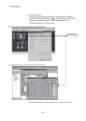
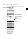
1.6.1 I/O No. for I/O modules and intelligent function modules
In the Multiple CPU system, the "0H" position(slot) of I/O No. which seen from the PLC
CPU is different from the position in the case of a standalone CPU. However, I/O No. of
the control module may be assigned independently for each CPU in the Motion CPU.
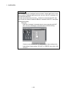
(1) "0H" position of I/O No.
(a) In the Multiple CPU system, the slots corresponding to the number of units
set by a multiple CPU parameter are occupied by the PLC CPU/Motion
CPU.
(b) I/O modules and intelligent function modules are installed in slots available
to the right of those occupied by the PLC CPU/Motion CPU.
(c) I/O No. of the control module may be assigned independently for each CPU
in the Motion CPU. I/O No. of the PLC CPU control modules are assigned
sequentially toward the right, starting from "0H" being the I/O module or
intelligent function module installed to the immediate right of the slots
occupied by the PLC CPU/Motion CPU.
(d) Notation of I/O No.
• Receiving of ON/OFF data by the Motion CPU is deemed input (PX), while
outputting of ON/OFF data from the Motion CPU is deemed output (PY).
• I/O No. is expressed in hexadecimal.
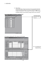
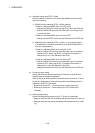
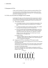
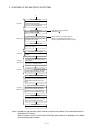
(2) Assignment of I/O No. to the Motion CPU control module
Mitsubishi recommends that I/O No. assignment be set as common consecutive
No. throughout all CPUs.
However, the I/O No. of the Motion CPUs control input modules, output modules
and input/output composite modules may also be set independently of the I/O
No. of the PLC CPU control modules.
(The I/O No. of the Motion CPU control modules are indicated with a PX/PY.)
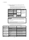
The I/O No. of the Motion CPU control modules are invalid during I/O Assignment
Settings of the PLC CPU.
Modules
controlled
by CPU
No. 2
QX41
PX0 to PX1F
(X0 to X1F)
Q173
CPU
(N)
Q02H
CPU
O
U
T
Power supply
module
QX41
X40 to X5F
12 3 450
I/O assignment
QY41
Y60 to Y7F
QY41
PY20 to PY3F
(Y20 to Y3F)
CPU
No. 1
CPU
No. 2
Modules
controlled
by CPU
No. 2
Modules
controlled
by CPU
No. 1
Modules
controlled
by CPU
No. 1