APP - 23
A
PPENDICES
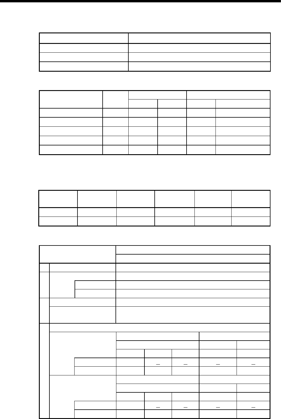
6) System setting
Setting items Description
Operation cycle setting Auto
Operation mode
M2000 is turned on with switch (Stop to Run)
Emergency shout down input
PX0
7) Latch range setting
Latch (1) Latch (2)
Item Symbol
Start End Start End
Internal relay M
Link relay B
Annunciator F
Data register D
Link register W
Latch (1) : It is possible to clear using the latch clear.
Latch (2) : Clearing using the latch clear is disabled.
(c) PLC module setting
Type of the
module
Number of
points
Occupation
device
Base Slot No.
I/O response
time
Input 16 000-00F CPU base unit 1 10[ms]
Output 16 010-01F CPU base unit 2
(4) Parameter setting of the Qn(H) CPU No.1
Qn(H) parameter
PC parameter item
Description
1 Number of CPU 2 modules
Operation mode The error operating mode in the CPU stop.
CPU No.1
All station stop by stop error
2
CPU No.2
All station stop by stop error
Out of group input settings The input condition outside the group is taken. 3
Out of group output
settings
The output condition outside the group is not taken.
Refresh setting
Send range for each CPU CPU side device
Shared CPU memory G First device M2400
Setting No.1
CPU
Point Start End Start END
CPU No.1 0
CPU No.2 50 0800 0831 M2400 M3199
Send range for each CPU CPU side device
Shared CPU memory G First device D0
Setting No.2
CPU
Point Start End Start END
CPU No.1
0
4
CPU No.2
640 0832 0AB1
D0 D639


