3 - 13
3 COMMUNICATION BETWEEN THE PLC CPU AND THE MOTION CPU IN
THE MULTIPLE CPU SYSTEM
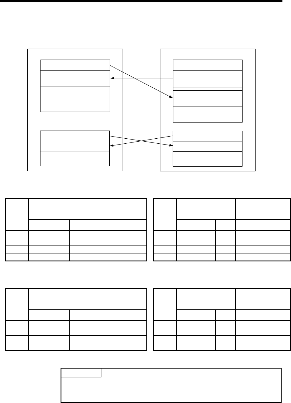
1) PLC CPU (1 module) + Motion CPU (1 module)
The outline operation and the automatic refresh setting are as follows.
Command device for
the Motion CPU
(768 points)
CPU No.1
(
PLC CPU
)
Data registers
CPU No.2
(
Motion CPU
)
M0
M768
M1824
M8191
Monitor device for
the Motion CPU
(1056 points)
Internal relays
Command device for
the Motion CPU
(118 points)
D0
D118
D758
D8191
Monitor device for
the Motion CPU
(640 points)
Data registers
Command device
(118 points)
D0
D640
D758
D8191
Monitor device
(640 points)
M0
M2000
M3055
M3072
M3839
M3840
M8191
Monitor device
(1056 points)
Command device
(768 points)
Internal relays
•
Automatic refresh setting 1
PLC CPU (CPU No.1) Motion CPU (CPU No.2)
Send range for each CPU CPU side device Send range for each CPU CPU side device
CPU share memory G Dev. starting M0 CPU share memory G Dev. starting *
CPU
Point Start End Start End
CPU
Point Start End Start End
No.1 48 M0 M767 No.1 48 M3072 M3839
No.2 66 M768 M1823 No.2 66 M2000 M3055
No.3 No.3
No.4
No.4
•
Automatic refresh setting 2
PLC CPU (CPU No.1) Motion CPU (CPU No.2)
Send range for each CPU CPU side device Send range for each CPU CPU side device
CPU share memory G Dev. starting D0 CPU share memory G Dev. starting *
CPU
Point Start End Start End
CPU
Point Start End Start End
No.1 118 D0 D117 No.1 118 D640 D757
No.2 640 D118 D757 No.2 640 D0 D639
No.3 No.3
No.4
No.4
POINT
Although it has set up so that 32 axes may be assigned in the above assignment
example, reduce the number of assignment automatic refresh points a part for the
number of axes to be used.


