


1 - 95
1 OVERVIEW
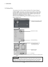
1.6.2 I/O No. of PLC CPU and Q173CPU(N)/Q172CPU(N)
In the Multiple CPU system, I/O No. is assigned to the PLC CPU/Motion CPU to
enable communication between the PLC CPU and Motion CPU using the following
instructions:
• The Multiple CPU dedicated instructions
• The Motion CPU dedicated instructions
• The Multiple CPU communication dedicated instructions
The I/O No. of the PLC CPU/Motion CPU are fixed based on the installed slots and
cannot be changed.
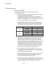
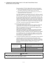
The table below lists the I/O No. of the PLC CPU/Motion CPU installed in the CPU
base unit of the Multiple CPU system.
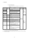
CPU installation position QCPU slot Slot 0 Slot 1 Slot 2
Head I/O number 3E00H 3E10H 3E20H 3E30H
The I/O No. of the PLC CPU/Motion CPU are used in the following cases:
• When writing data to the shared CPU memory of the self CPU using the S. TO
instruction.
• When reading data from the shared CPU memory of the other CPU using the FROM
instruction.
• When reading data from the shared CPU memory of the other CPU using an
intelligent function module device (U
\G )
• When reading device data directly from the Motion CPU from the PLC CPU using
the "S(P). DDRD" instruction.
• When writing device data directly to the Motion CPU from the PLC CPU using the
"S(P).DDWR" instruction.
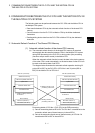
REMARK
• Refer to Chapter "3. COMMUNICATION BETWEEN THE PLC CPU AND THE
MOTION CPU IN THE MULTIPLE CPU SYSTEM" for communication between
the PLC CPU and the Motion CPU.