3 - 22
3 COMMUNICATION BETWEEN THE PLC CPU AND THE MOTION CPU IN
THE MULTIPLE CPU SYSTEM
3.4 Shared CPU Memory
Shared CPU memory is used to transfer data between the CPUs in the Multiple CPU
system and has a capacity of 4096 words from 0H to FFFH.
Shared CPU memory has four areas: "self CPU operation data area", "system area",
"automatic refresh area" and "user-defined area."
When the automatic refresh function of shared CPU memory is set, the area
corresponding to the number of automatic refresh points starting from 800H is used as
the automatic refresh area.
The user-defined area begins from the address immediately next to the last address of
the automatic refresh area.
If the number of automatic refresh points is 18 (12H points), the area from 800H to
811H becomes the automatic refresh area and the area after 812H becomes the user-
defined area.
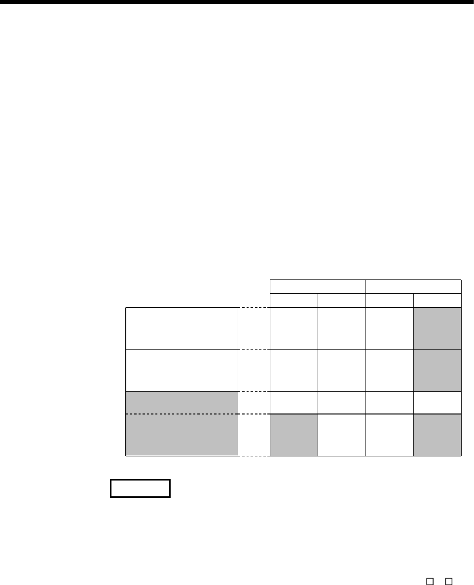
The diagram below shows the structure of shared CPU memory and accessibility from
a PLC program.
Self CPU operation
data area
System area
Automatic refresh area
User-defined area
Shared CPU memory
0H
1FFH
to
200H
7FFH
to
800H
FFFH
to
Self CPU
Write
Not allowed
Allowed
Read
Write
Read
Not allowed
Not allowed
Not allowed
Not allowed
Not allowed
Not allowed
Not allowed
Not allowed
Not allowed Not allowed
Allowed
Allowed
Not allowed
(Note-1)
(Note-2)
Other CPU
Allowed
REMARK
(Note-1) : Use the S. TO instruction to write to the user-defined area of the self CPU
in the PLC CPU.
Use the MULTW instruction to write to the user-defined area of the self
CPU in the PLC CPU. (Refer to Section 1.3.4(4) for the conditions which
can use the MULTW instruction.)
(Note-2) : Use the FROM instruction/intelligent function module device (U
\G ) to
read the shared memory of the Motion CPU from the PLC CPU.
Use the MULTR instruction to read the shared memory of other CPU in
the Motion CPU. (Refer to Section 1.3.4(4) for the conditions which can
use the MULTR instruction.)


