


9 - 18
9 MOTION CONTROL PROGRAMS
[Program example]
A program which made the current value change control of the synchronous encoder
shaft is described as the following conditions.
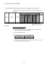
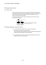
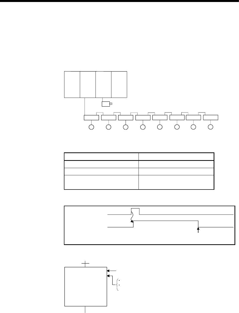
(1) System configuration
The current value change control of the synchronous encoder shaft P1 is
executed.
QX10Q172
EX
Q173
CPU
(N)
Q02H
CPU
Axis 1
M
Axis 2
M
AMP
M M
AMP
M M
AMP
M M
AMP
Axis 3
Axis 4
Axis 5
Axis 6
Axis 7
Axis 8
AMP
AMP
AMPAMP
P1 axis
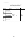
(2) The current value change control conditions
(a) The current value change control conditions are shown below.
Item Setting
Servo program No. 10
Synchronous encoder No. 1
Current value change address
Indirect designation
using D1500, D11501
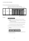
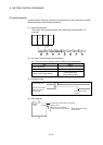
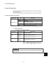
(3) Operation timing
CHG
A
-E instruction
Synchronous encoder
shaft current value
changing flag
Current value change
completion
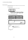
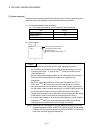
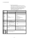
(4) Servo program
CHGA-E
Synchronous encoder shaft current value
change control
Axis 1, D1500
< K10 >
Synchronous encoder No. .......... 1
Current value change address ... Indirect designation using
D1500, D1501