


Chapter 1. System Description 9
1st ed., 6/30/04 - 312579601
Task Recovery/Termination
Task recovery is concerned with resource recovery, possible retry operations, and the
logging of software-detected errors. Terminations can be considered a special case of
recovery where resources must still be recovered but no retry or logging is necessary. The
SCP supports the most common ESTAE and ESTAI options and major SDWA fields.
Recovery includes a disabled and enabled (scheduled task) mode. The resources being
recovered are files to be closed, storage to be released, tasks to be terminated, and
messages and scheduled interrupts to be cancelled.
Host Software Component (HSC)
The HSC runs as an application program in the SCP environment. The HSC source code is
compiled by StorageTek.
The HSC accepts requests from the tape management interface (TMI) (see “Tape
Management System (TMS)” below) and drives the library hardware.
Tape Management System (TMS)
The TMS uses the IUCV interface to communicate with the virtual machine. It provides a
front end between the HSC and the user, and provides allocation, mount, and scratch pool
services. The HSC provides the TMS with mount/dismount service and assists it in
allocation for those volumes and drives which are under library control.
Note: In this document ‘‘TMS’’ is used to refer to any tape management system and not
any particular product.
Operators and Utility Users
Operators use CP SMSG to communicate with the SCP via the CP Message System
Service (*MSG). Utility users communicate with the SCP via punch spool files containing
special control statements. The authorization services allows only specified users to access
either of these interfaces; unauthorized users are disconnected from the service machine
when any attempt is made to communicate with the subsystem.
Virtual Machine Configuration
Within a VM host system the following virtual machines (users) exist:
• operator(s)
• ACS service machine (SCP and HSC)
• TMS service machine
• administrator(s)
• TMS requestors.
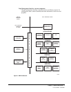
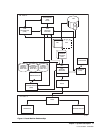
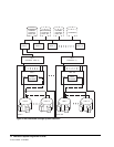
Various illustrations are provided to show relationships. Figure 2 on page 11 illustrates the
relationship of users to each other and the virtual machine and hardware relationships.
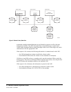
Figure 3 on page 12 illustrates how the library data sets may be shared by multiple,
dissimilar host systems.