


5-20 Field Control™ Genius® Bus Interface Unit User’s Manual
–
October 1999 GFK-0825F
5
Add Modules and Assign References
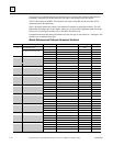
The steps for configuring an I/O module depend on whether or not the
module is present at the time of configuration. “Intelligent” modules (see the
list below) must be present to be configured, conventional I/O modules do
not have to be present.
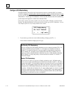
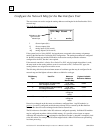
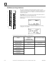
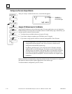
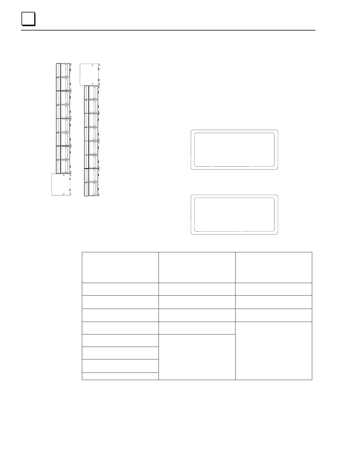
Slot Number
refers to the location of the module in the station, relative to
the Bus Interface Unit. See the illustration at left.
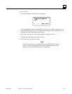
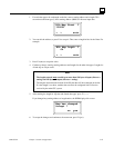
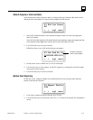
If the slot has not already been configured, after configuring the I/O map, the
HHM displays:
S:1 Empty
< > tgl read
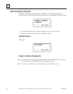
If the slot has previously been configured, the HHM shows the existing
configuration. For example:
S:1 Q:16
Q01785-Q01800
< > del zoom
See the instructions on the next two pages to configure the slot.
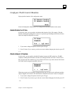
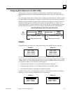
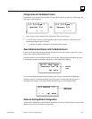
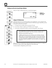
Module Present, Read/Zoom to
configure:
Module Present, Read/Enter to
configure, or
No Module Present,
Select Special I/O to configure:
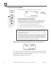
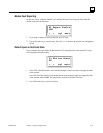
No Module Present,
Select Generic I/O to configure:
Analog 16-Point Grouped Input
Module: IC670ALG240
Analog 8 volt In Discrete Input 4/8
Analog 8-Point Voltage Input
Module:IC670ALG281
Analog 8 cur In Discrete Input 16
Analog 16-Point Voltage Input
Module: IC670ALG282
Analog 4 cur Out Discrete Output 4/8
Analog Voltage Output Module:
IC670ALG310
ESCP 8 Disc Out
Analog Current-source Output
Module: IC670ALG330
Analog RTD Input Module:
IC670ALG620
Analog Thermocouple Input Module:
IC670ALG630
Micro Field Processor: IC670MFP100
Combo Disc 10/06
Discrete Output 16
1
2
3
4
5
6
7
8
0
1
2
3
4
5
6
7
8
0
BIU
BIU