


8-2 Field Control™ Genius® Bus Interface Unit User’s Manual
–
October 1999 GFK-0825F
8
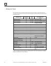
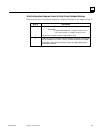
Datagram Types
The table below shows the primary datagrams that may be acted upon by the Bus Interface Unit.
The table lists the types of device that can send each datagram, and the resulting action taken by the
Bus Interface Unit.
Datagram Type Subfunction
Code
Sent
From
Bus Interface Unit
Action
Read Identification 00 BC, HHM send Read ID Reply
Read Configuration 02 BC, HHM send Read Configuration Reply
Write Configuration 04 BC, HHM process (possibly send
configuration changes)
Assign Monitor 05 BC process
Begin Packet Sequence 06 BC, HHM start sequence
End Packet Sequence 07 BC, HHM end/check sequence
Pulse Test 10 HHM send Pulse Test Complete
Clear All Faults 13 BC, HHM process
Set Status Table Address 17 BC, HHM process
Force BSM 1A BC, HHM process (send config. change)
Unforce BSM 1B BC, HHM process (send config. change
when last point is unforced)
Switch BSM 1C BC process
Set MFP Operating Mode 21 BC
Recalibrate Analog Module 21 BC
Read Map 2A BC, HHM send Read Map Reply
Write Map 2C BC, HHM process-autoconfigure
Set Operating Mode 39 BC process
Read I/O Forces 40 BC send Read I/O Forces Reply
Read Slot Diagnostics 42 BC send Read Slot Diagnostics
Reply
A PLC or computer can send a datagram to the Bus Interface Unit in the same manner as sending a
datagram to an I/O block or Bus Controller.