


C-8 Field Control™ Genius® Bus Interface Unit User’s Manual
–
October 1999 GFK-0825F
C
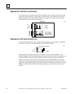
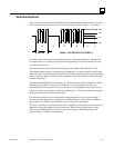
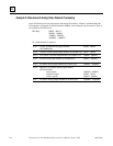
The half cycle pulse width, when measured between the positive and negative receiver thresholds,
denoted as Tp/2 in the figure, will vary along the waveform due to dispersion, and resembles a
frequency shift.. The digital input filter essentially is a band pass filter which looks at the half cycle
timing Tp/2, and the duration above the thresholds, Tw. The limits are:
•
Tp/2 = 0.6 Tp(normal) maximum
•
Tw = 0.188 Tp(normal) minimum
These measurements can be taken when evaluating the maximum length of an unspecified cable.
Dispersion is much less of a problem with fiber optic links since the media is much wider
bandwidth, and therefore has less distortion.
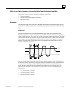
Propagation Delay
The propagation delay is caused by travel time of the signal down the cable. Typical signal velocity
in data grade cables is around 65- 78% of the speed of light. This requires about 3 microseconds to
travel a 2000 foot long bus. This is about half a bit time at 153,6 Kb. This skew could affect the
bus access sequence since only one bit of quiet bus (skip) time is usually allocated between
transmission of adjacent addresses. (Refer to Bus Access Time section below.) The signal must
reach all devices on the bus within the period of one bit. Propagation delay causes the ultimate
limitation in bus length, even with ideal media. Propagation speed through fiber optic is not
significantly different than wire, and delays through the interfaces must be accounted for.
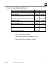
Serial Data Format
The Genius protocol is designed to produce maximum throughput of data by using a minimum
overhead of control and synchronizing characters.
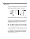
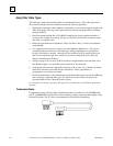
Each character is 11 bits long, comprising a start bit (always 0), next a control bit, followed by 8
bits of data, sent LSB first. The last bit is a stop bit, always 1. Successive characters are sent with
no time space between them. The control bit is used to signal the type of character being sent. A 1
indicates a control character, and 0 a data character.
A minimum transmission is comprised of a start character, one or more data characters, and a stop
character. The Start character data contains the address and whether the transmission is directed to
a specific address or a broadcast to all. The End character contains the CRC-6 checksum. More
complex transmissions may have additional start and end of block characters to break up the
message into “blocks” of data (not to be confused with Genius I/O “Blocks”). For example, a Bus
Controller can send device specific messages (blocks of data) to all devices on the bus during one
transmission cycle.