


GFK-0825F Chapter 3 Installation 3-11
3
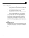
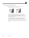
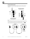
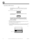
Making Bus Connections
1. Connect Serial 1 to the Serial 1 terminals of the previous device and the next device.
2. Connect Serial 2 to the Serial 2 terminals of the previous device and the next device.
3. Connect Shield In to Shield Out of the preceding device. Connect Shield Out to Shield In of
the next device. If the Bus Interface Unit is the first device on a bus, Shield In can be left
unconnected. If it is the last device on a bus, Shield Out can be left unconnected.
Serial 1
Serial 2
Shield In
Shield Out
Start
of Bus
End
of Bus
Terminating
Resistor
Serial 1
Serial 2
Shield In
Shield Out
Terminating
Resistor
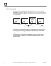
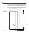
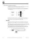
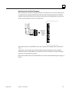
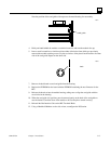
Terminating a Bus
If either bus will terminate at the Bus Interface Unit, connect a 75, 100, 120, or 150-ohm
terminating resistor across the Serial 1 and Serial 2 terminals. Appendix C lists the correct
impedance to use for each recommended type of bus cable.
Note: If the Bus Interface Unit will be powered up when not connected to a properly-terminated
bus, connect a 75-ohm resistor across its Serial 1 and Serial 2 terminals to assure proper powerup.
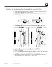
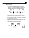
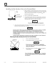
Using Prefabricated Terminating Resistors
Prefabricated molded connectors with terminating resistors are available for 75 ohms (catalog
number IC660BLM508) and 150 ohms (IC660BLM506).
They can be used with conventional bus cable and with the cables with pre-molded connectors.
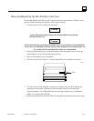
Attach the prefabricated resistor to the female cable end as shown below.
Slide prefabricated resistor onto
female cable end
Underside of prefabricated
resistor, showing projection