


8-12 Field Control™ Genius® Bus Interface Unit User’s Manual
–
October 1999 GFK-0825F
8
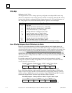
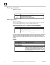
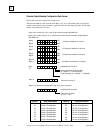
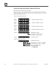
Discrete Output Modules Configuration Data Format
Specify the actual slot number and a length of 30.
The reference address is the location in the BIU's I, Q, AI, or AQ memory that is used by the
module's data. Specify only one address, typically in the discrete output (Q) table. Set the other
address selection bytes to all zeros.
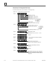
unlabelled bits must be 0
B
y
tes 0 to 3 must be: 51 hex
,
0
,
0
,
0 for all modules except IC670MDL730
B
y
tes 0 to 3 must be 20 hex, 0, 0, 0 for Electronic Short Circuit Protection Output Module,
IC670MDL730
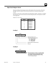
76543210
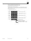
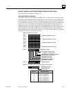
Byte
12
Output Default or Hold Last State
(0 = default, 1 = hold last state)
Fault Reporting (0 = enabled, 1 = disabled)
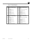
Bytes 14 to 29: Circuit Configuration. For each circuit, content is:
76543210
Byte 13
reserved (must be 0)
unlabelled bits must be 0
76543210
Output Default State
(0 = off, 1 = on)
76543210
76543210
Byte 4 LSB
MSB
Byte 5
I Reference Address or all zeros
76543210
76543210
Byte 6 LSB
MSB
Byte 7
76543210
76543210
Byte 8
LSB
MSB
Byte 9
76543210
76543210
Byte 10
LSB
MSB
Byte 11
Q Reference Address or all zeros
AI Reference Address or all zeros
AQ Reference Address or all zeros
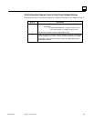
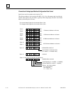
(Byte #) Byte Description (Byte #) Byte Description
14
15
16
17
18
19
20
21
Circuit 1 Configuration
Circuit 2 Configuration
Circuit 3 Configuration
Circuit 4 Configuration
Circuit 5 Configuration
Circuit 6 Configuration
Circuit 7 Configuration
Circuit 8 Configuration
22
23
24
25
26
27
29
29
Circuit 9 Configuration
Circuit 10 Configuration
Circuit 11 Configuration
Circuit 12 Configuration
Circuit 13 Configuration
Circuit 14 Configuration
Circuit 15 Configuration
Circuit 16 Configuration