


1-10 Field Control™ Genius® Bus Interface Unit User’s Manual
–
October 1999 GFK-0825F
1
Using Field Control in a CPU Redundancy System
Most systems use only one Bus Controller and CPU to control the I/O on the Genius bus. CPU
redundancy, which can be used for backup CPU/Bus Controller protection in critical applications,
is described in detail in the Genius documentation. The section that follows here summarizes how
Field Control products can fit into a Genius CPU Redundancy system.
CPU/Bus Controller Redundancy: Overview
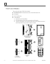
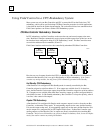
In CPU redundancy, two Bus Controllers on the same bus can send control outputs at the same
time. Both Bus Controllers automatically receive inputs and fault reports from all devices on the
bus that have been configured as being in “CPU Redundancy” mode. The Bus Controllers must
use serial bus addresses (device numbers) 30 and 31.
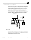
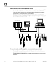
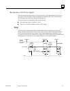
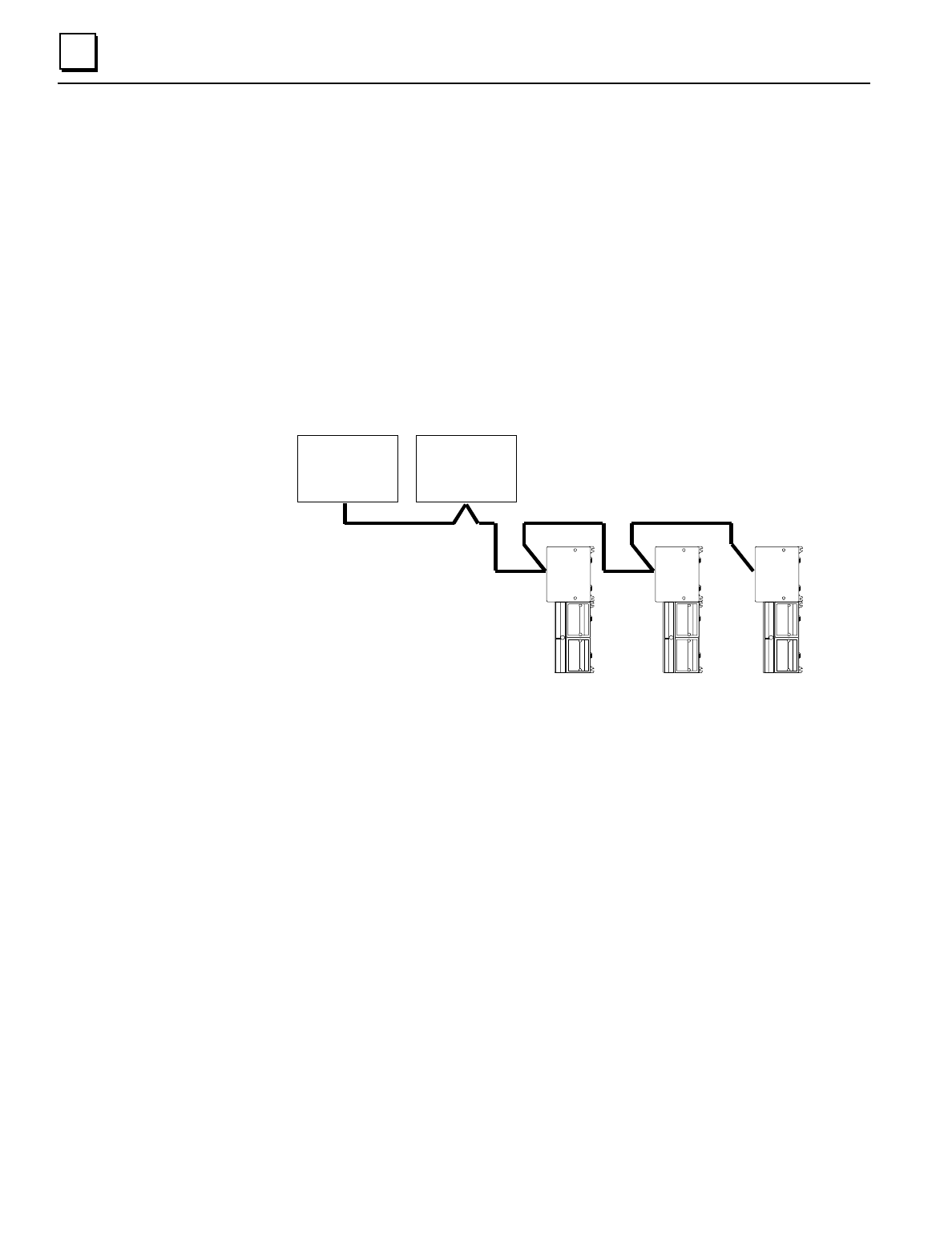
Field Control stations can be used on a bus controlled by redundant CPUs/Bus Controllers.
Bus
Controller
(Device 30)
Bus
Controller
(Device 31)
46471
How the two sets of outputs from the dual CPUs are handled by a Bus Interface Unit depends on
whether the Bus Interface Unit is set up for Hot Standby or Duplex redundancy.
If the station
contains any analog modules, the only form of CPU redundancy permitted is Hot Standby.
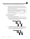
Hot Standby CPU Redundancy
A Bus Interface Unit configured for Hot Standby mode is normally controlled by the Bus
Controller assigned to serial bus address 31. If no outputs are available from 31 for three bus
scans, the Bus Interface Unit accepts outputs from the Bus Controller assigned to serial bus address
30. If outputs are not available from either Bus Controller, outputs go to their configured defaults
or hold their last state. In Hot Standby redundancy, Bus Controller-31 always has priority; when it
is on-line, it has control of the outputs.
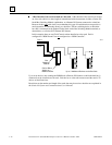
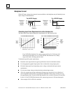
Duplex CPU Redundancy
A Bus Interface Unit configured for Duplex mode compares outputs it receives from the two Bus
Controllers, to determine if they match. If corresponding outputs are the same, the Bus Interface
Unit sets the output to that state. If corresponding outputs are not the same, the Bus Interface Unit
sets the output to its configured ON or OFF Duplex Default State. If either Bus Controller stops
sending outputs to a Bus Interface Unit, its outputs are directly controlled by the remaining Bus
Controller.
Only discrete I/O modules can operate in Duplex redundancy mode; do not use Duplex
mode if the station contains any analog I/O modules.