


8-8 Field Control™ Genius® Bus Interface Unit User’s Manual
–
October 1999 GFK-0825F
8
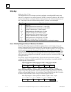
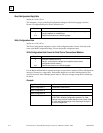
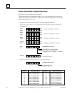
Read Configuration Reply Data
Subfunction Code: 03 hex
This datagram is a reply to the Read Configuration datagram. The following pages show the
formats of configuration data for Field Control devices.
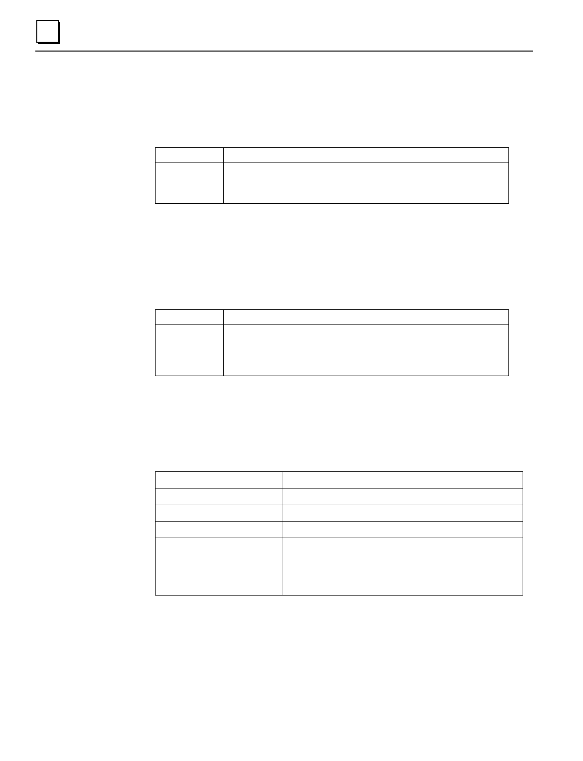
Byte # Description
0 Slot (corresponds to slot supplied in Read Configuration message
1 Length (depends on module type)
2-N Data format shown on the following pages
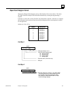
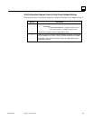
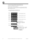
Write Configuration Data
Subfunction Code: 04 hex
The Write Configuration datagram is used to send configuration data. Content of the data is the
same as the Read Configuration Reply. Do not send partial configuration data.
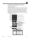
Write Configuration Data Format for Field Control Conventional Modules
Byte # Description
0 Slot (Bus Interface Unit is 0)
1 Length (must match the length for the specific device whose
configuration will be written.)
2-N Data format shown on the following pages
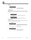
Use the Begin and End Packet sequence messages to ensure that a sequence of Write Configuration
messages is treated as a single entity. Each packet should be in slot order. Multiple packets for a
slot must also be in order. Multiple packets must be 128 bytes in length except the last which may
be shorter.
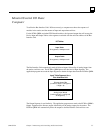
Example:
Begin Packet Sequence (subfunction code 06 hex)
Write Configuration 1 (subfunction code 04 hex)
Write Configuration 2
Write Configuration N
End Packet Sequence (subfunction code 07 hex). This contains the total number
of BYTES in all Write Configuration packets. For Field
Control (only) the End Packet Sequence has 2 bytes. Byte
0 is the least significant byte of the data length and byte 1
is the most significant.