


8-28 Field Control™ Genius® Bus Interface Unit User’s Manual
–
October 1999 GFK-0825F
8
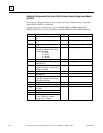
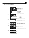
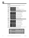
Group Move 1
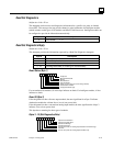
The diagram below shows the sequence of group mode configuration data for Group Move 1,
Move 1 and Move 2. The format for subsequent moves is the same.
76543210
76543210
Byte 28
Byte 29
76543210
76543210
Byte 30
Byte 31
76543210
76543210
Byte 32
Byte 93
76543210
76543210
Byte 34
Byte 35
Source Slot
Destination Slot
Which Sweeps Data Group Will Be Moved
Hold Last State/Defailt
Source Table Segment Selector
Destination Table Segment Selector
Source Offset in bytes, LSB
Source Offset in bytes, MSB
Byte Length of Data, LSB
Byte Length of Data, MSB
Source Table Segment Selector
Destination Table Segment Selectot
Source Offset in bytes, LSB
Source Offset in bytes, MSB
Byte Length of Data, LSB
Byte Length of Data, MSB
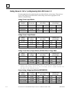
76543210
76543210
Byte 36
Byte 37
76543210
76543210
Byte 38
Byte 39
76543210
76543210
Byte 40
Byte 41
76543210
76543210
Byte 42
Byte 43
76543210
76543210
Byte 44
Byte 45
76543210
76543210
Byte 46
Byte 47
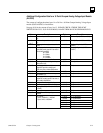
Destination Offset in bytes, LSB
Destination Offset in bytes, LSB
Destination Offset in bytes, MSB
Group Move 1
Submove 1
Submove 2
Destination Offset in bytes, MSB
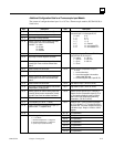
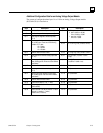
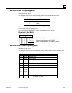
The high byte of address + 2 of the pointer is not used; it must be zero. The low byte of address + 2
specifies the type of memory where the Status Pointer will be located.
For This Memory Type: Enter This Number:
I discrete input table 16
Q discrete output table 18
R register memory 8
AI analog input table 10
AQ analog output table 12