


GFK-0825F Chapter 8 Datagrams 8-17
8
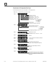
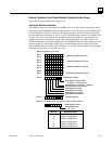
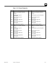
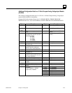
Bytes 14 - 61: Channel Configuration
(Byte #) Byte Description (Byte #) Byte Description
14 Input 1:
circuit configuration (see above) 38 Input 3:
circuit configuration (see above)
15 reserved 39 reserved
16, 17 low scaling point, eng. units
(lsb in byte 16)
40, 41 low scaling point, eng. units (lsb in byte 40)
18, 19 high scaling point, eng. units
(lsb in byte 18)
42, 43 high scaling point, eng. units
(lsb in byte 42)
20, 21 low scaling point, digital counts
(lsb in byte 20)
44, 45 low scaling point, digital counts
(lsb in byte 44)
22, 23 high scaling point, digital counts
(lsb in byte 22)
46, 47 high scaling point, digital counts
(lsb in byte 46)
24, 25 output default value (lsb in byte 24) 48, 49 output default value (lsb in byte 48)
26 Input 2:
circuit configuration (see above) 50 Input 4:
circuit configuration (see above)
27 reserved 51 reserved
28, 29 low scaling point, eng. units
(lsb in byte 28)
52, 53 low scaling point, eng. units (lsb in byte 52)
30, 31 high scaling point, eng. units
(lsb in byte 30)
54, 55 high scaling point, eng. units
(lsb in byte 54)
32, 33
low scaling point, digital counts
(lsb in byte 32)
56, 57
low scaling point, digital counts
(lsb in byte 56)
34, 35 high scaling point, digital counts
(lsb in byte 34)
58, 59 high scaling point, digital counts
(lsb in byte 58)
36, 37 output default value (lsb in byte 36) 60, 61 output default value (lsb in byte 60)