


GFK-0825F Chapter 8 Datagrams 8-25
8
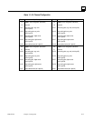
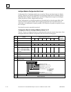
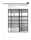
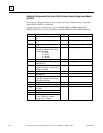
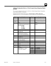
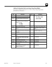
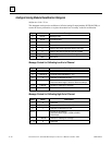
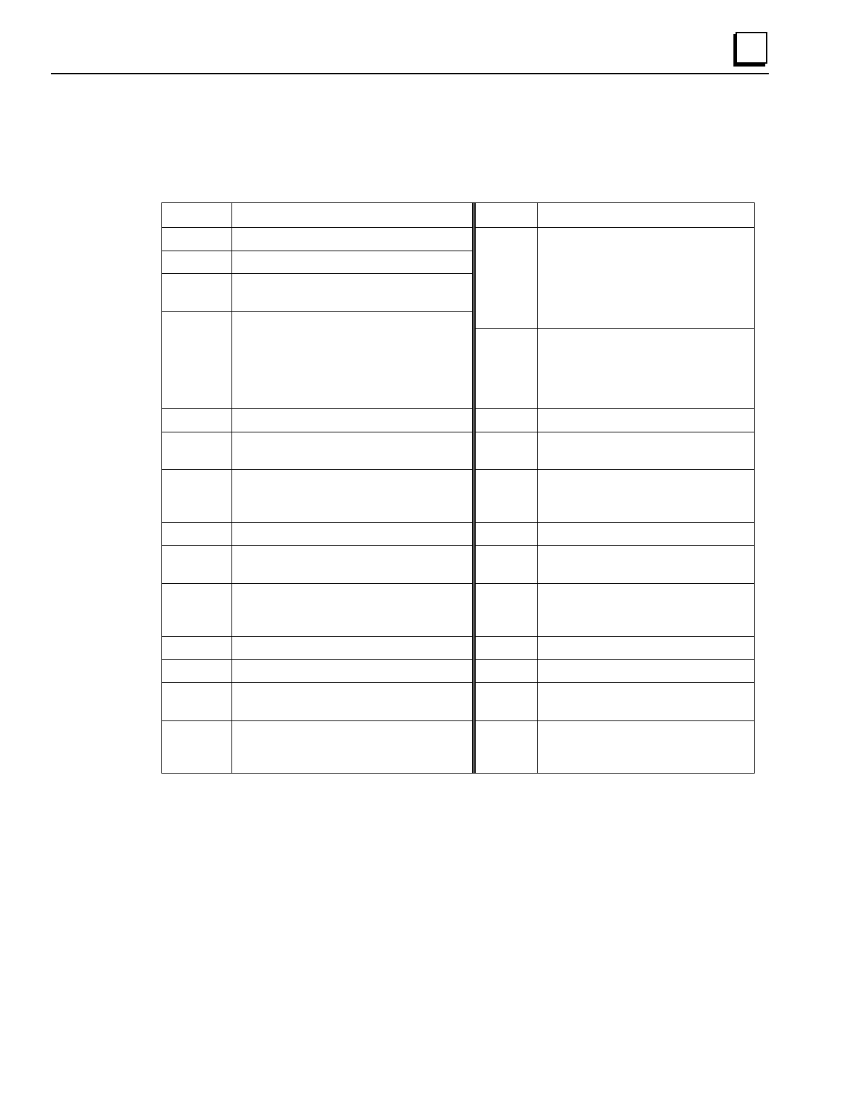
Additional Configuration Data for an Analog Voltage Output Module
The content of configuration data bytes 14 to 119 for an Analog Voltage Output module
(IC670ALG310) is listed below.
Byte Description Byte Description
14 Number of input reference parameters (1)
15 Number of output reference parameters (2)
16, 17 Byte length of diagnostic discrete input data
(0 - 3)
40, 41 Ch1 Range:
0 span -10,000 to +10,000,
units -10,000 to +10,000
1 span 0 to +10,000,
units 0 to +10,000
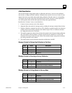
18, 19 Memory type for the module's diagnostic input
bits, usually type I. Enter one of the following
numbers: 16 = I table
18 = Q table
10 = AI table
12 = AQ table
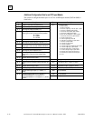
42, 43 Ch 1 Low Eng. Units (-32768 to +32767)
20, 21 Relative offset from start of table 44, 45 Ch 1 High Eng. Units (-32768 to +32767)
22, 23 Byte length of the module's analog output data
(0 - 16)
46, 47 Ch1 Low Span (-10,000 to +10,000
<=high)
24, 25 Memory type for the module's analog output
data, usually type AQ. Enter one of the numbers
listed above.
48, 49 Ch1 High Span
(-10,000 to +10,000 >=low)
26, 27 Relative offset from start of table 50 - 59 Ch 2 parameters
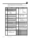
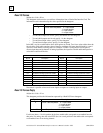
28, 29 Byte length of module's control output bits
(0 - 2)
60 - 69 Ch 3 parameters
30, 31 Memory type for the module's control output
bits, usually type Q. Enter one of the numbers
listed above.
70 - 79 Ch 4 parameters
32, 33 Relative offset from start of table. 80 - 89 Ch 5 parameters
34, 35 Local Default Output (0 = off, 1 = hold) 90 - 99 Ch 6 parameters
36, 37 BIU command timeout in milliseconds
(500 to 65535)
100-109 Ch 7 parameters
38, 39 Active Channels. One bit per channel. For each
channel, 0 = inactive, 1 = active)
Default is 0xFF, all active).
110-119 Ch 8 parameters