


B-2 Field Control™ Genius® Bus Interface Unit User’s Manual
–
October 1999 GFK-0825F
B
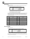
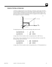
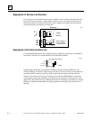
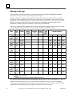
Suppression for Devices in an Enclosure
For a group of devices installed in an enclosure, the MOVs can be installed at the point where the
power lines enter the enclosure. Ideally, MOVs should be used at each cabinet in the system for
maximum protection. The following illustration shows suppression on both power lines and the
communications bus for modules in an enclosure.
Enclosure
Power
to
Modules
Short Length of
Bus to All Bus
Interface Units
46461
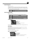
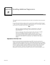
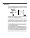
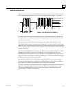
Suppression at the Communications Line
For an individual Bus Interface Unit, suppression can be supplied by connecting two small MOVs
from Serial 1 and Serial 2 to the Bus Interface Unit's Shield Out terminal:
S1
S2
SHLD IN
SHLD OUT
(bus cable not shown)
MOVs
46463
Suitable MOVs include Harris part number V220MA2A, Panasonic ERZ-CO5FK221U, and
Siemens 505K140. If necessary, higher energy-rated devices can also be used. It is important to be
sure that the MOV leads do not cause any shorts between the serial data and shield connectors.
Chapter 2 of the
Genius I/O System and Communications Manual
(GEK-90486-1) describes the
noise-rejection and filtering capabilities of the Genius bus. It explains bus wiring practices for all
applications. That chapter also gives additional instructions for installing a bus outdoors or between
buildings, including recommendations for adding suppression at the point where the bus enters a
building.