


GFK-0825F Chapter 5 Station Configuration 5-9
5
Select a Series Six or Series Five PLC Reference Address
If the network controller is not a Series Six PLC or Series Five PLC, no entry is necessary here.
Press F4 (entr) to go on.
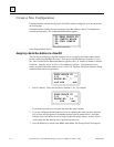
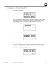
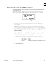
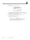
If the network controller is a Series Six PLC or Series Five PLC, an I/O or register reference
address must be assigned to the Bus Interface Unit. This is done on the screen shown below.
Stat Tbl Addr
00000
< > IO6 entr
shows reference type
1. The F3 key toggles the selection of Series Six I/O memory, Series Five I/O memory, or
register memory.
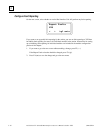
If I/O memory is used, the amount required is equal to the number of bits of discrete data
PLUS analog data. Each analog reference used consumes 16 points. Data is stored beginning
at the assigned I/O reference. In the Input Table, the sequence is: discrete inputs, then analog
inputs. In the Output Table, the sequence is discrete outputs, then analog outputs. This is
illustrated in chapter 3.
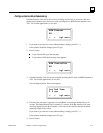
If register memory is used, an amount is required that is equal to the total number of bytes of
input data PLUS all of the output data. Data is stored beginning at the assigned register
reference. The sequence is: discrete inputs, then analog inputs, then discrete outputs, and
analog outputs last. See chapter 3 for more information.
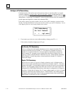
2. Key in the number of the block's beginning I/O or register reference. This may be:
Series Six I/O 1 to 993
Series Five I/O 1 to 2041
Registers 1 to 16383 (or upper limit of CPU, which may be less)
3. Press the F4 (Entr) key.