


1-12 Field Control™ Genius® Bus Interface Unit User’s Manual
–
October 1999 GFK-0825F
1
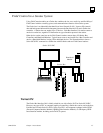
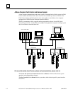
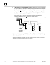
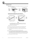
A Bus Interface Unit can be located on a bus stub.
A Bus Interface Unit can also be located
on a bus stub, which is a short length of unterminated cable downstream of either a Genius I/O
block/Bus Switching Module combination, or a Remote I/O Scanner connected to a dual bus.
Because the bus stub cable itself is not redundant, this type of installation does not provide as
much protection as connecting directly to a dual bus. The bus switching device to which the
bus stub is connected can be another Genius block with a Bus Switching Module attached, as
shown below, or a Series 90-70 Remote I/O Scanner.
In this example, there are two Field Control stations installed on a bus stub. Each is
configured as “BSM Present” but not configured as a “BSM Controller”.
Bus A
Bus B
Bus
Switching
Module
Genius Block
Acting as a
BSM Controller
Up to 7 Additional Devices on the Bus Stub
46474
Up to seven devices (not counting the BSM/block or Remote I/O Scanner to which the dual bus is
connected) can be installed on a bus stub. Each device on a bus stub counts toward the total of 32
devices on the Genius bus.
Restrictions on the number and length of bus stubs that may be used on a dual bus are explained in
the
Genius I/O System and Communications User's Manual.