


GFK-0825F Chapter 3 Installation 3-9
3
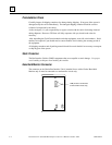
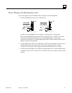
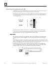
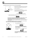
Power Wiring to the Bus Interface Unit
Note: Do not apply power until the BIU module is installed on the Terminal Block.
1. Connect an appropriate power source as shown below.
+
-
24 VDC
Low Voltage
Connections
(IC670GBI002)
115VAC or
125VDC
High Voltage
Connections
(IC670GBII02)
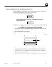
For BIU version IC670GBI102, if a DC supply is used the polarity is not important.
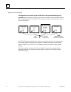
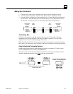
BIU version IC670GBI102 provides internal overvoltage protection. Terminal 4 is normally
connected to frame ground (terminal 3) by a factory-installed jumper. If overvoltage
protection is not required
or
is supplied upstream this feature can be disabled by removing the
jumper, leaving pin 4 unconnected.
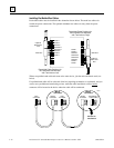
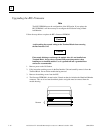
2. Use one AWG #14 (2.1mm
2
) or two AWG #16 (1.3mm
2
) wires per terminal. The wires into a
terminal should be the same type and size. Wires must be copper conductors rated for
75 degrees C (167 degrees F) only. Suggested torque for the terminal screws is 9 in/lbs.
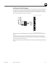
3. Connect the ground terminal to the conductive mounting panel with a 4-inch maximum length
of AWG #14 (avg 2.1mm
2
) or larger wire. Use hardware such as star washers to ensure ground
integrity.