


8-26 Field Control™ Genius® Bus Interface Unit User’s Manual
–
October 1999 GFK-0825F
8
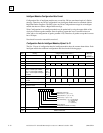
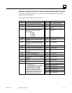
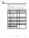
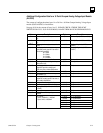
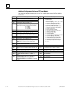
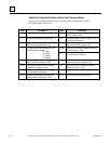
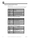
Additional Configuration Data for a Micro Field Processor Module
The content of configuration data bytes 14 to 43 for a Micro Field Processor module
(IC670MFP100) is listed below.
Byte Description Byte Description
14 Number of input reference parameters (2) 28, 29 Byte length of the number of outputs from the BIU to
the MFP's I table. (0 - 64)
15 Number of output reference parameters (2) 30, 31 BIU table to get data for the MFP's I table. Enter one
of the numbers listed above.
16, 17 Byte length of number of inputs to BIU from the
MFP's discrete output (Q) table (0 - 64)
32, 33 Byte offset of from the start of the selected BIU table
to get data for the MFP's I table (0 - 255)
34, 35 Byte length of the number of outputs from the BIU to
the MFP's AI table. (0 - 254)
18, 19 BIU table to place Q data from the MFP. Enter
one of the following numbers:
16 = I table
18 = Q table
10 = AI table
12 = AQ table
36, 37 BIU table to get data for the MFP's AI table. Enter
one of the numbers listed above.
20, 21 Byte offset from the start of the selected BIU
table to put MFP Q table data. (0 - 255)
38, 39 Byte offset of from the start of the selected BIU table
to get data for the MFP's AI table (0 - 255)
22, 23 Byte length of the number of inputs to the BIU
from the MFP's AQ table. (0 - 254)
40 Number of checksums. O means do not check
program logic match. (0 - 255)
24, 25 BIU table to put AQ table from the MFP. Enter
one of the numbers listed above.
41 Byte checksum of the MFP ladder logic.
26, 27 Byte offset from the start of the selected BIU
table to put MFP AQ table data. (0 - 255)
42, 43 Word LRC checksum of MFP ladder logic.