


8-20 Field Control™ Genius® Bus Interface Unit User’s Manual
–
October 1999 GFK-0825F
8
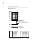
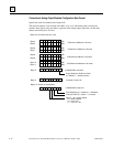
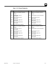
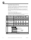
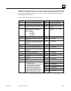
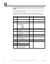
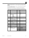
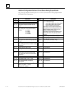
Additional Configuration Data for an 8 Point Grouped Analog Voltage Input Module
(ALG281)
The content of configuration data bytes 14 to 149 for an 8 Point Grouped Analog Voltage Input
module (IC670ALG281) is listed below.
See page 8-18 for the content of bytes 0 to 13. PLEASE CHECK; I THINK THE OCMT
WRITEUP FOR 22,23, 28,29 WAS WRONG; I MADE THEM MATCH OTHER MODULES.
Byte
Description Byte Description
14
Number of input reference parameters
(2)
40, 41 Ch1 Low Span (-10000 to +10000)
15
Number of output reference parameters
(1)
42, 43 Ch1 High Span (-10000 to +10000)
16, 17
Byte length of analog input data (default
is 16)
44, 45 Ch 1 Low Eng. Units (-32768 to +32767)
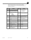
18, 19
Memory type for the module's analog
input data, usually type AI. Enter one of
the following numbers:
16 = I table
18 = Q table
10 = AI table
12 = AQ table
46, 47 Ch 1 High Eng. Units (-32768 to +32767)
20, 21
Relative offset from start of table 48, 49 Ch1 Low Alarm
22, 23
Byte length of discrete diagnostic input
data (default is 5)
50, 51 Ch1 High Alarm
24, 25
Memory type for the module's diagnostic
input bits, usually type I. Enter one of the
numbers listed above.
52-65 Ch 2 parameters
26, 27
Relative offset from start of table 66-79 Ch 3 parameters
28, 29
Byte length of module's control output
bits (default is 1)
80-93 Ch 4 parameters
30, 31
Memory type for the module's control
output bits, usually type Q. Enter one of
the numbers listed above.
94-107 Ch 5 parameters
32, 33
Relative offset from start of table 108-121 Ch 6 parameters
34 (bit 4)
Line Frequency (0 = 50Hz, 1 = 60Hz) 122-135 Ch 7 parameters
34 (bits
0,1)
Filtering Method (0 = None, 1 = 10mS,
2 = 20mS)
136-149 Ch 8 parameters
35
reserved
36, 37
Active Channel Bit Map 1 bit per channel
38, 39
Ch1 Range:
1 span -10000mV to +10000mV
2 span 0mV to +10000mV