


GFK-0825F C-1
The Genius Serial Bus
This appendix describes the selection and operating characteristics of the bus cable that links Genius
devices. This information supercedes the equivalent text portion of chapter 2 of
The Genius I/O System
and Communications Manual
(GFK-90486), “The Communications Bus”
.
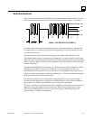
A Genius serial bus consists of two or more Genius devices, and (usually) the bus cable that
connects them. A single block or bus controller with a Hand-held Monitor directly attached,
properly terminated with a 75 Ohm resistor, is considered the smallest possible Genius
communications bus.
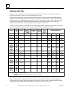
Wiring Guidelines
Four types of wiring may be encountered in a typical factory installation:
1. Power wiring - the plant power distribution, and high power loads such as high horsepower motors.
These circuits may be rated from tens to thousands of KVA at 220 VAC or higher.
2. Control wiring - usually either low voltage DC or 120 VAC of limited energy rating. Examples are
wiring to start/stop switches, contactor coils, and machine limit switches. This is generally the
interface level of the Genius discrete I/O.
3. Analog wiring - transducer outputs and analog control voltages. This is the interface level to Genius
I/O analog blocks.
4. Communications and signal wiring - the communications network that ties everything together,
including computer LANs, MAP, and Genius I/O and communications bus.
These four types of wiring should be separated as much as possible to reduce the hazards from
insulation failure, miswiring, and interaction (noise) between signals. A typical PLC system with
Genius I/O may require some mixing of the latter three types of wiring, particularly in cramped
areas inside motor control centers and on control panels. In general, it is acceptable to mix the
Genius bus cable with the I/O wiring from the blocks, as well as associated control level wiring.
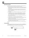
All noise pickup is cumulative, depending on both the spacing between wires, and the distance
span they run together. I/O wires and Genius bus cable can be placed randomly in a wiring trough
for lengths of up to 50 feet. If wiring is cord-tied (harnessed), do not include the bus cable in the
harness, since binding wires tightly together increases the coupling and mechanical stress that can
damage the relatively soft insulation of some serial cable types.
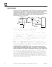
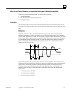
Wiring external to equipment and in cable trays, should be separated following NEC practices. The
pickup over long-distance runs with adequate spacing consists of common mode and ground
voltage differences. These are rejected due to the differential transmission mode of the Genius bus
and the bus isolation transformers built into each Genius I/O block.
C
Appendix