


3-12 Field Control™ Genius® Bus Interface Unit User’s Manual
–
October 1999 GFK-0825F
3
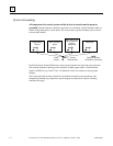
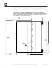
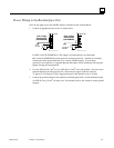
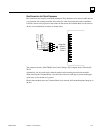
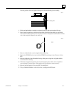
Installing Pre-Molded Bus Cables
Pre-molded cables must be installed in the orientation shown below. The main bus cable exits
toward the power connections. The optional redundant bus cable exits away from the power
connections.
Shield Out
Shield In
Serial 2
Serial 1
Serial 1
Serial 2
Shield In
Shield Out
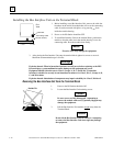
Premolded Cable Positions for
Bus Interface Unit Mounted
with Terminals on Left
Premolded Cable Positions for
Bus Interface Unit Mounted
with Terminals on Right
Main Bus
Optional
Redundant
Bus
Main Bus
Optional
Redundant
Bus
Shield Out
Shield In
Serial 2
Serial 1
Serial 1
Serial 2
Shield In
Shield Out
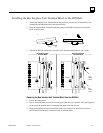
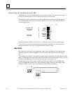
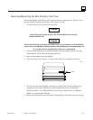
Where two prefabricated cable ends meet at the same device, join the male and female ends (see
below).
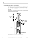
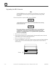
If a prefabricated cable will be at the end of the bus (requiring termination, as explained), and you
want to use a prefabricated terminating resistor, make the cable installation so that a female
connector will be located at the device where the cable will be terminated.
46492
male
connector
female
connector
female
connector
male
connector
terminating re
sistor (male)
Mating
connectors
Mating
connectors
Connect to
Last Device