


7-6 Field Control™ Genius® Bus Interface Unit User’s Manual
–
October 1999 GFK-0825F
7
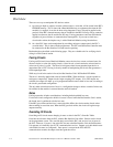
Monitor/Control I/O Data:
Series 90 PLC
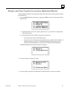
If the host is a Series 90 PLC, I/O data can be displayed in the PLC's reference tables. The PLC's
reference tables displays will include those portions of the PLC's I, Q, AI, and AQ memory being
used by a Bus Interface Unit.
In the reference tables for the PLC, these inputs are displayed along with other system inputs.
When the programmer is attached to the PLC, the programmer software can override or toggle the
I/O data and cause a change.
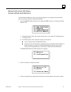
Monitor/Control I/O Data:
Series Six PLC or Series Five PLC
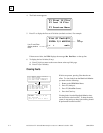
For a Series Six or Series Five PLC, I/O data for a Field Control station may be configured to use
either I/O or register memory. To utilize the data correctly, it is necessary to know the slot number
of each module, and the amount of input and output data it has. Data lengths are equal to the
amounts configured for I, AI, Q, and AQ. For discrete data, 16 points = 16 I/O references or 1
register. For analog data, 1 channel = 16 I/O references or 1 register.
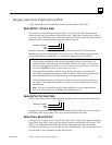
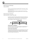
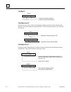
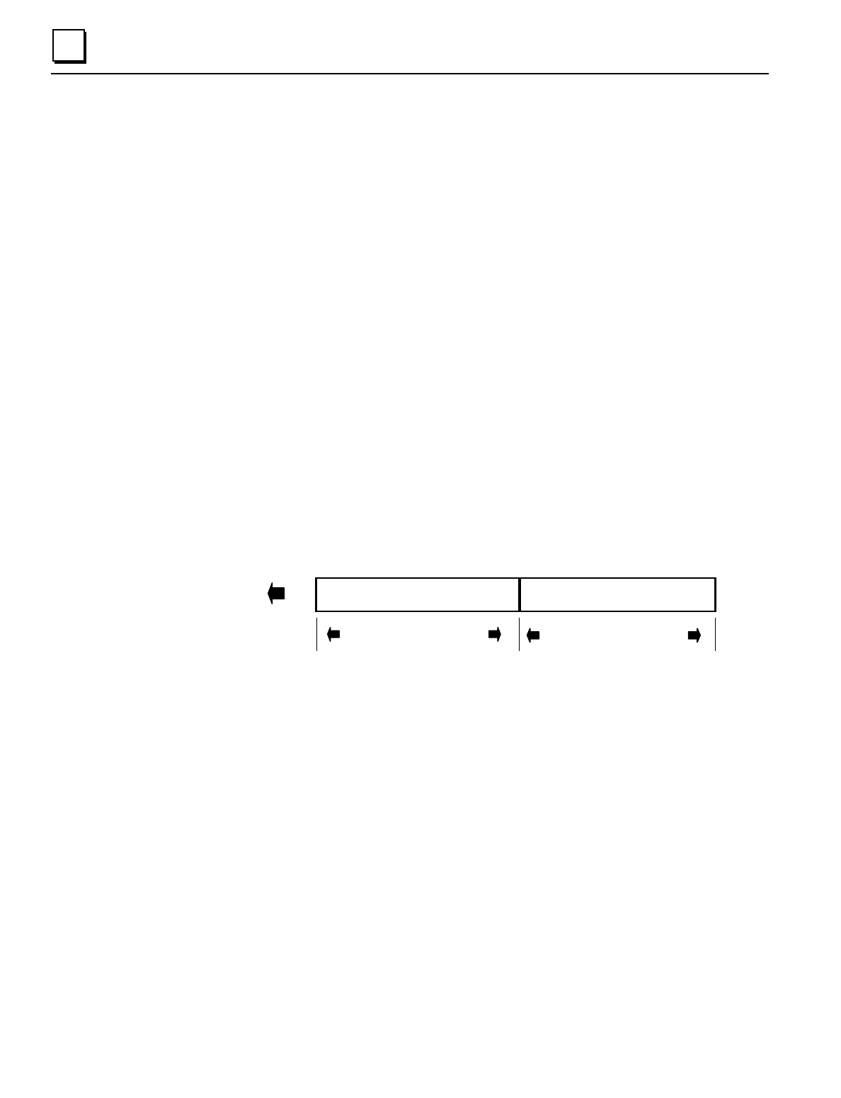
Input Data Message
(up to 128 bytes)
discrete inputs analog inputs
Configured I Length
Configured AI Length
To CPU
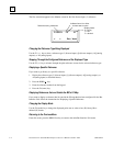
Field Control Data in I/O Table Memory
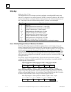
In I/O memory, data from a Bus Interface Unit is stored beginning at the assigned I/O reference. In
the Input Table, the sequence is: discrete inputs then analog inputs. In the Output Table, the
sequence is discrete outputs then analog outputs.
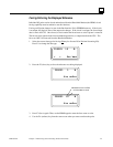
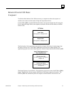
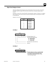
Field Control Data in Register Memory
If Series Six or Series Five register memory is used for data from the Bus Interface Unit, an amount
is required that is equal to the total number of bytes of input data PLUS output data. The data is
stored beginning at the assigned register reference. The sequence is: discrete inputs, then analog
inputs, then discrete outputs, and analog outputs last. Data lengths are equal to the amounts of I,
AI, Q, and AQ configured for the Bus Interface Unit.