


4-16 Field Control™ Genius® Bus Interface Unit User’s Manual
–
October 1999 GFK-0825F
4
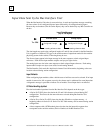
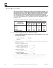
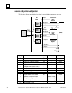
Overview of Synchronous Operation
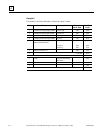
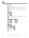
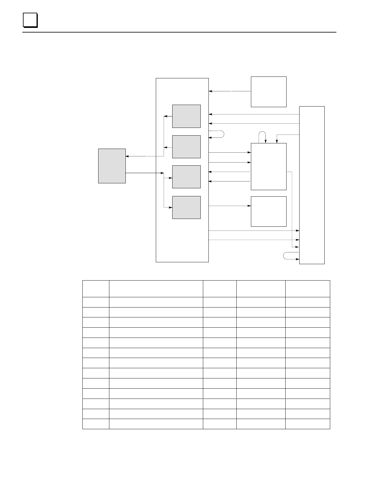
The following diagram and table show how data is handled during synchronous operation.
Genius
Network
BIU
Tables
Smart
Module
Micro
Field
Processor
Conventional
Output
Module
Conventional
Input
Module
I
Discrete
Inputs
AI
Analog
Inputs
Q
Discrete
Outputs
AQ
Analog
Outputs
6. to
network
7. from
network
1. Inputs
2. All inputs
3. Groups
3.
4. Groups
5. All outputs
8. All inputs
9. Groups
10. Outputs
11. All outputs
12. Groups
12.
12.
4.
4.
Sweep
Step
Action Forces, if
mapped
No Network Cannot Read
Module
1 Inputs from conventional modules yes - defaults
2 All inputs from intelligent modules yes - defaults
3 Groups not from MFP: to BIU tables yes - defaults
4 Groups to MFP yes - -
5 All outputs to MFP (starts solution) - - -
6 Move to network - n/a n/a
7 Move from network yes n/a n/a
8 All inputs from MFP (gets solution) yes - defaults
9 Groups from MFP to BIU tables yes - defaults
10 Outputs to conventional modules - defaults at step 7 -
11 All outputs to intelligent modules - defaults at step 7 -
12 Groups to intelligent modules - defaults at step 7 defaults
(13) Data displayed on HHM - - -