


GFK-0825F Chapter 3 Installation 3-3
3
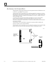
System Wiring Guidelines
Four types of wiring may be encountered in a typical factory installation:
1. Power wiring - the plant power distribution, and high power loads such as high
horsepower motors. These circuits may be rated from tens to thousands of KVA at 220
VAC or higher.
2. Control wiring - usually either low voltage DC or 120 VAC of limited energy rating.
Examples are wiring to start/stop switches, contactor coils, and machine limit switches.
This is generally the interface level of the Genius discrete I/O.
3. Analog wiring - transducer outputs and analog control voltages. This is the interface level
to Genius I/O analog blocks.
4. Communications and signal wiring - the communications network that ties everything
together, including computer LANs, MAP, and Genius I/O and communications bus.
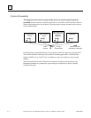
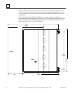
These four types of wiring should be separated as much as possible to reduce the hazards from
insulation failure, miswiring, and interaction (noise) between signals. A typical PLC system with
Genius I/O may require some mixing of the latter three types of wiring, particularly in cramped
areas inside motor control centers and on control panels. In general, it is acceptable to mix the
communications bus cable with the I/O wiring from the blocks, as well as associated control level
wiring. All noise pickup is cumulative, depending on both the spacing between wires, and the
distance span they run together. I/O wires and communications bus cable can be placed randomly
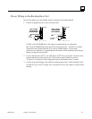
in a wiring trough for lengths of up to 50 feet. If wiring is cord-tied (harnessed), do not include the
bus cable in the harness, since binding wires tightly together increases the coupling and mechanical
stress that can damage the relatively soft insulation of some serial cable types.
Wiring which is external to equipment, and in cable trays, should be separated following NEC
practices.
Installing Additional Suppression
It is possible some installations might exceed the surge immunity capabilities specified in chapter
1. This is most likely in outdoor installations or where the power source is from another building or
ground system. It is prudent to provide local transient protection.
Appendix B describes installation of additional suppression at the power and communications
lines.