


8-14 Field Control™ Genius® Bus Interface Unit User’s Manual
–
October 1999 GFK-0825F
8
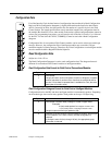
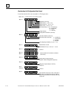
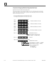
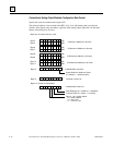
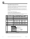
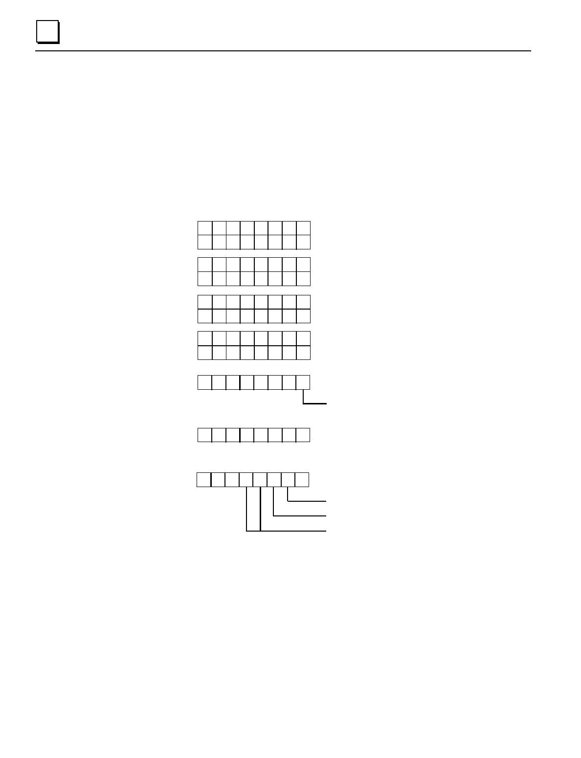
Conventional Analog Input Modules Configuration Data Format
Specify the actual slot number and a length of 126.
The reference address is the location in the BIU's I, Q, AI, or AQ memory that is used by the
module's data. Specify only one address, typically in the analog input (AI) table. Set the other
address selection bytes to all zeros.
unlabelled bits must be 0
For current module, bytes 0 to 3 must be: 32 hex, 0,0,0
For voltage module, bytes 0 to 3 must be: 34 hex, 0,0,0
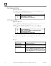
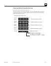
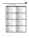
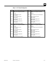
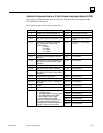
76543210
Byte 12
Input Default or Hold Last Value
(0 = default, 1 = hold last value)
76543210
Byte 13
reserved
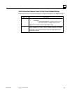
7 6 543210
Fault Reporting (0 = enabled, 1 = disabled)
Channel Active (0 = active, 1 = inactive)
unlabelled bits must be 0
Bytes 14, 28, 42, 56, 70, 84, 98, 112 (see below)
Range: 00 = 0mA to 20mA
01 = 4mA to 20mA
10 = 0V to 10V
11 = -10V to +10V
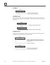
76543210
76543210
Byte 4 LSB
MSB
Byte 5
I Reference Address or all zeros
76543210
76543210
Byte 6
LSB
MSB
Byte 7
76543210
76543210
Byte 8 LSB
MSB
Byte 9
76543210
76543210
Byte 10 LSB
MSB
Byte 11
Q Reference Address or all zeros
AI Reference Address or all zeros
AQ Reference Address or all zeros