


5-64 Field Control™ Genius® Bus Interface Unit User’s Manual
–
October 1999 GFK-0825F
5
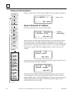
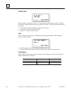
Configure an RTD Input Module
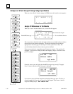
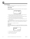
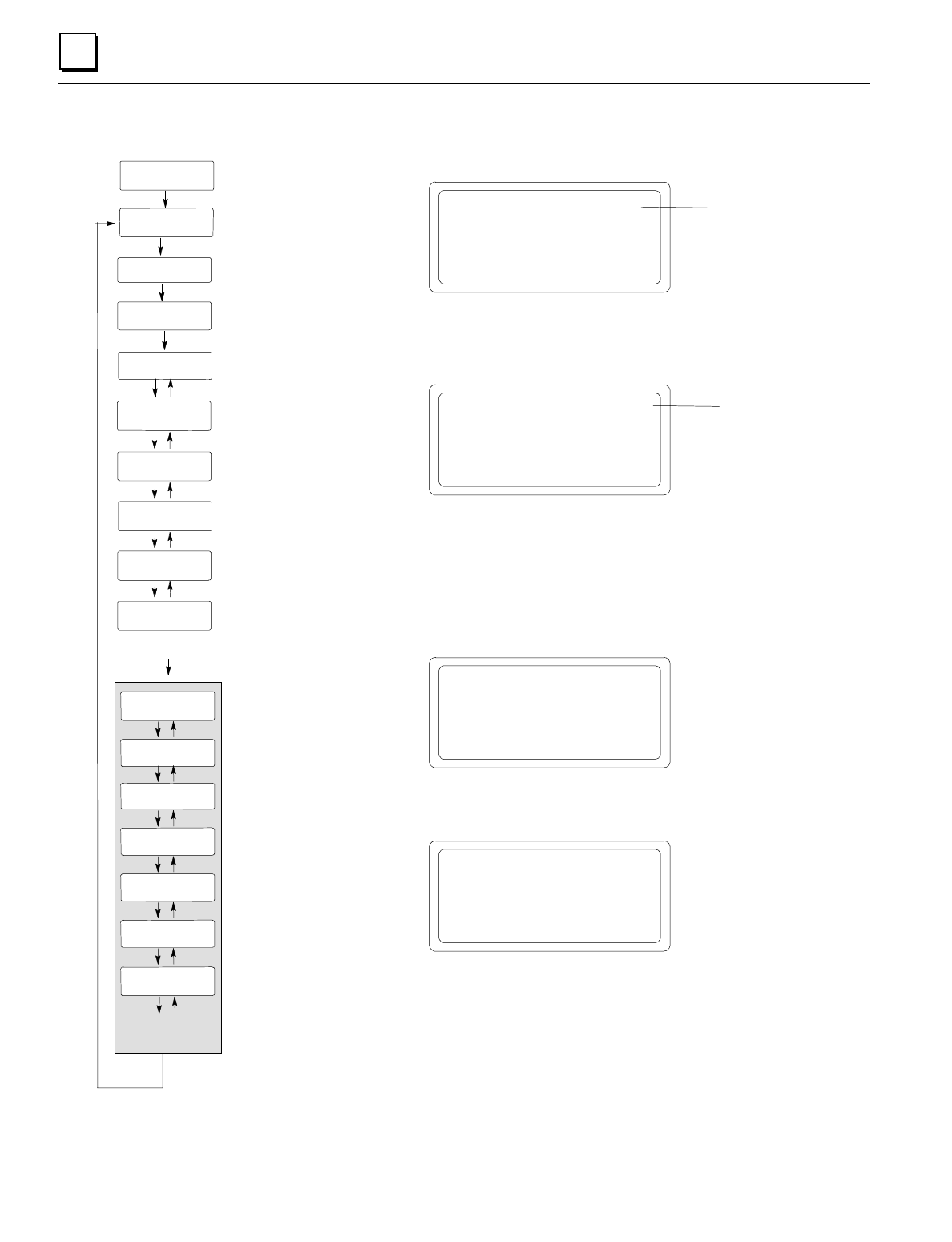
When you select “Read” from the empty slot HHM screen, this module screen appears:
S:4 ALG620 *.*
< > del zoom
Module version
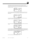
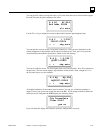
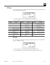
Assign I/O References for the Module
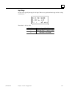
Press F4 to zoom into the slot. A screen like this appears:
Number of
references for
this module type
S:4 AI *AI:004
AI01311-01314
< > chg entr
This screen shows the default table and length and the next available reference address
for that reference type. The length is displayed in appropriate units (AI and AQ in
words, Q and I are bits). An asterisk indicates that the reference is not yet defined. If the
present selection is acceptable, press F4 (enter) to accept it. The asterisk will disappear.
If you prefer to change the BIU table mapping, length, or reference value, press F3
(change).
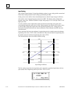
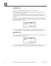
S:4 AI AI
Select table
chg entr
From this screen, you can display the other data types by pressing F3 (toggle). Press F4
(enter) when the desired data type is displayed.
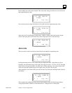
S:4 AI AI:004
Select length
chg entr
If you want to enter a different length for the displayed data type, press F3 (clear) to
clear the length field. Enter the new length from the keypad. If you enter an invalid
length, the HHM prompts: BAD LENGTH ERR After “entering” the correct length, the
offset (starting reference) screen appears. The BIU automatically supplies the next
available address in the selected table.
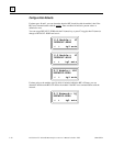
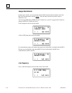
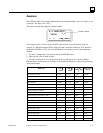
S1 CH 1
ACTIVE
S1 CH1 UNITS
DEG C
S1 CH1 ALARM HI
00800
S1CH1RTDTYPE
100 PT 385
S1CH1WIRETYP
3 WIRE
S1 RESIST.1
00000
S1 CH1 ALARM LO
-00200
F2
F1
F2
F1
F2
F1
F2
F1
F2
F1
F2
F1
F2
F1
Repeat for
Other Channels
F2
S1 LINE FREQ
60 HZ
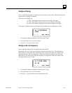
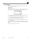
S1: Q *Q:08
Q00001-00008
S1 AQ *AQ:004
AQ00001-00004
S1: I *I:032
I00001-00032
S1 Network->%Q
DEFAULT ZERO
S1 Module-> %I
DEFAULT ZERO
S1: ALG620
F4
S1: AI *AI004
AI00001-00004
F4, F2
F4, F2
F4, F2
F4, F2
F1
S1 Module-> %AI
DEFAULT ZERO
F2
F1
F2
F1
F2
F1
F2
F1
F1, F2 select
channels
F4
S1 CH 1 CONFIG