


4-10 Field Control™ Genius® Bus Interface Unit User’s Manual
–
October 1999 GFK-0825F
4
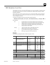
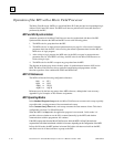
Input Data Sent by the Bus Interface Unit
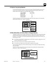
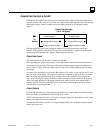
When the Bus Interface Unit takes its turn on the bus, it sends one input data message containing
the latest values for all configured discrete inputs followed by all configured analog inputs.
Because they are broadcast (like all Genius inputs), they can be obtained by any Bus Controller on
the bus.
Input Data Message
(up to 128 bytes)
discrete inputs analog inputs
Configured I Length
Configured AI Length
AI starting reference dataI starting reference data
T
o CPU
The data lengths are equal to the configured lengths of I and AI data selected for the Bus Interface
Unit (regardless of the host CPU type or the actual amount of output data needed for the modules
physically present in the station). Either length may be zero.
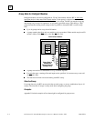
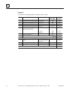
The discrete inputs appear in the input message in the same sequence as their assigned input
references. Each discrete input module occupies one byte per eight circuits.
The analog inputs are also in the same sequence as their assigned input references. Each analog
input module occupies two bytes (one word) for each analog channel.
The Bus Interface Unit sends this data from its internal I and AI memories, beginning at the start
locations selected during station configuration.
Input Defaults
When configuring input modules, either a default state or hold last state can be selected. If an input
module is removed or fails to operate correctly, the chosen state is substituted for actual input data.
A diagnostic message is provided to indicate loss of module. Forced input data is not affected.
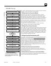
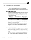
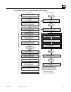
I/O Data Handling by Host
How the host handles input data from the Bus Interface Unit depends on the host type:
A Series 90-70 PLC places the data in the %I and %AI references selected during PLC
configuration. These must be the same references selected during Bus Interface Unit
configuration.
A Series Six or Series Five PLC places the data into I/O table or register memory. A
beginning address in Series Six or Series Five I/O Table memory can be entered during station
configuration.
A host computer with a PCIM module places the data into the input table segment that
corresponds to the serial bus address (Device Number) of the Bus Interface Unit.