


3-10 Field Control™ Genius® Bus Interface Unit User’s Manual
–
October 1999 GFK-0825F
3
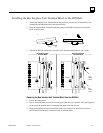
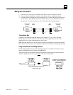
Connecting the Communications Bus
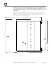
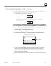
The Bus Interface Unit Terminal Block has a two sets of bus terminals. The terminals in the center
portion of the terminal block are for the main bus cable; they are always used.
The outermost set of bus terminals is for an optional redundant (dual) bus cable. The Bus Interface
Unit Terminal Block has built-in bus switching capability;
do not attach a Bus Switching Module in
a dual bus application
.
Main Bus
Connections
Redundant Bus
Connections
(optional)
Shield Out
Shield In
Serial 2
Serial 1
46462
Serial 1
Serial 2
Shield In
Shield Out
B1
B2
Bin
Bout
Aout
Ain
A2
A1
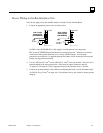
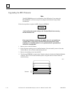
Terminals accept one AWG #14 (2.1mm
2
) or two AWG #14 (avg 2.1mm
2
cross section) copper
75 deg. C
(167 deg. F) wires. Each terminal can accept solid or stranded wires. The wires on any
terminal should be the same type. The suggested torque is 9 in/lbs (1 Nm).
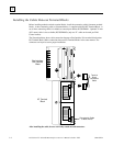
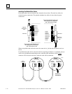
Bus Cables
Bus connections can be made using standard bus cables (cable specifications for the Genius bus are
detailed in Appendix C. Also see Appendix C for a discussion of the characteristics of the Genius
bus.
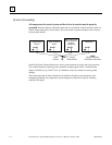
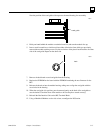
When making bus connections, the maximum exposed length of unshielded wires should be two inches
(5cm). For added protection, each shield drain wire should be insulated with spaghetti tubing to prevent
the Shield In and Shield Out wires from touching each other, or the signal wires.
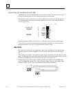
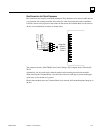
For applications using 150 ohm cables, prefabricated cables are available in 15" (IC660BLC001)
and 36" (IC660BLC003) lengths. These cables terminate in mating connectors that simplify wiring
between I/O blocks. The 36" cable is recommended for Field Control installations.
SHD
OUT
SHD
IN
SER
2
SER
1
SHD
OUT
SHD
IN
SER
2
SER
1