


2-4 Field Control™ Genius® Bus Interface Unit User’s Manual
–
October 1999 GFK-0825F
2
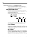
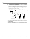
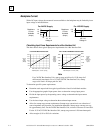
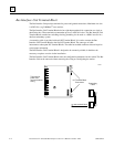
Backplane Current
With a DC input voltage, the amount of current available to the backplane may be limited by lower
input voltage as indicated below.
18
19
1.0
1.2
1.4
21
Voltage In
Backplane
Current
(Amps)
Available
For 24VDC Supply
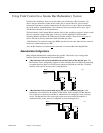
105
1.8
2.0
110
Voltage In
Backplane
Current
(Amps)
Available
For 125VDC Supply
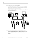
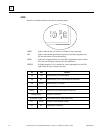
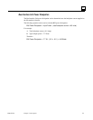
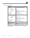
Calculating Input Power Requirements for a Bus Interface Unit
The charts below show typical input power requirements for a Bus Interface Unit.
Total Backplane Current (Amps)
Typical
Input
Power
(Watts)
0.25 0.50 0.75 1.00 1.20 1.400
3.4
5.5
7.7
10.0
12.3
14.1
15.9
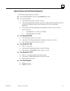
Total Backplane Current (Volts)
Typical
Input
Power
(Watts)
for DC
Inputs
0.50 1.501.00 2.0
0
3.0
8.25
13.5
18.75
24.0
Typical
Input
Power
(Volt/Amps)
for AC
Inputs
For 24VDC Bus Interface Unit
For 115VAC/125VDC Bus Interface Unit
7.0
17.25
27.5
37.75
48.0
Note
For a 24VDC Bus Interface Unit, start-up surge at full load is 15-50 Amps for 3
milliseconds (maximum). For a 115VAC/125VDC Bus Interface Unit, startup
surge at full load is 20 Amps peak for 3mS.
To determine specific system requirements:
Determine total output load from typical specifications listed for individual modules.
Use the appropriate graph of input power above to determine average input power.
Divide the input power by the operating source voltage to determine the input current
requirements.
Use the lowest input voltage to determine the maximum input current.
Allow for startup surge current requirements. Startup surge current levels are a function of
source impedance and, therefore, are installation-dependent. Startup surge currents can vary
for approximately 3mS. For the 24VDC Bus Interface Unit, variance is between 25A and 50A.
For the 115VAC/125VDC Bus Interface Unit, startup surge current is 20A maximum peak.
Allow margins (10% to 20%) for variations.