


1-6 Field Control™ Genius® Bus Interface Unit User’s Manual
–
October 1999 GFK-0825F
1
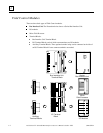
Configuration for Field Control
Configuration is an important part of the process of setting up a Field Control station. It establishes
the following features:
For the Bus Interface Unit:
Genius serial bus address
Baud rate for Genius bus communications
Fault reporting to the host
Use of the Bus Interface Unit as a bus switching device in a dual (redundant) bus system
Redundancy mode for CPU redundancy
Configuration protection
For I/O Modules:
I/O addressing
Whether faults will be reported to the host
Hold Last State for inputs or outputs
Output defaults
Range selection for analog modules
Scaling for analog modules
Alarm limits for analog modules
For a Micro Field Processor:
Reference addresses
Data Lengths
A Bus Interface Unit and I/O modules can be fully configured using a Hand-held Monitor.
Optionally, a previously-configured Bus Interface Unit can be reconfigured using datagrams.
For more information about configuration, please refer to:
Chapter 5 of this manual (
HHM Configuration
). A Genius Hand-held Monitor, version 4.6
(IC660HHM501J ) or later, can be used to configure a Bus Interface Unit. HHM configuration
instructions are given in chapter 5.
In addition, chapter 8 of this manual (
Datagrams)
explains how the configuration of a Bus
Interface Unit can be completed or changed by sending it Write Configuration datagrams.
The
Series 90 Micro Field Processor User's Manual
(GFK-1171), which describes the Micro
Field Processor (IC670MFP100), and provides installation procedures, operation information, and
diagnostics information.
If the system host is a Series 90™70 PLC, the Genius Bus Interface Unit must be included in the
system configuration as a device on the bus. Please see the programming software documentation
for instructions.