


Index
GFK-0825F Index-1
A
Alarm limits
Analog Grouped Input module, 5-47, 5-55, 5-63
Analog input module, 5-33
RTD module, 5-70
Thermocouple module, 5-78
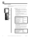
Alignment tabs, 2-7
Analog Current Output Module
configuration instructions, 5-81, 5-90
Analog Grouped Input Module
alarm limits, 5-47, 5-55, 5-63
channel active, 5-45, 5-53, 5-60, 5-95
configuration instructions, 5-40, 5-48, 5-56
data defaults, 5-42, 5-50, 5-58, 5-93
I/O references, 5-40, 5-48, 5-56, 5-90
input filtering, 5-43, 5-51, 5-59, 5-94
input range, 5-45, 5-53, 5-61, 5-96
input scaling, 5-46, 5-54, 5-62, 5-97
line frequency, 5-43, 5-51, 5-59
Analog Input Module
alarm limits, 5-33
Channel Active, 5-30
configuration format for datagram, 8-14
configuration steps, 5-29
current/voltage range, 5-31
default/hold last state, 5-34
fault reporting, 5-30
scaling values, 5-32
Analog inputs, 4-10
Analog Output Module
channel active, 5-37
channel fault reporting, 5-37
configuration format for datagram, 8-16
configuring, 5-35
current/voltage ranges, 5-38
scaling, 5-39
Analog outputs, 4-11
Analog Voltage Output Module
channel active, 5-86
data defaults, 5-84
I/O references, 5-81
scaling range, 5-87
Attenuation, C-7
Auxiliary I/O Terminal Block, 1-4
B
Backplane current, 2-4
Backplane scan times, 4-7
Baud rate
configuration, 5-8
selection guidelines, C-10
BIU
backing up outputs with MFP, 4-19
BIU data types, 4-3
BIU scanning frequency for Group Data, 5-106
BIU sweep
selective, 4-4
BIU Terminal Block
description, 2-8
functional specifications, 2-9
introduction, 1-3
BSM Controller, 5-11
BSM Present, 5-11
Bus
access, C-9
ambient specifications, C-11
baud rate, C-10
cable characteristics, C-6
cable types, C-4
cable with pre-molded connectors, 3-10
connecting to BIU Terminal Block, 3-10
connectors, 3-13
electrical interface, C-2
general transceiver specifications, C-3
length, C-10
lightning transients, C-11
noise, effect on data, C-11
outdoors, C-11
prefabricated cables, terminated, C-6
removing during operation, 3-13
repeaters, using, C-7
scan time, 4-9, 4-12
serial data format, C-8
surge suppression, C-11
termination, 3-11
unspecified cable type, using, C-7
using other cable types, C-6
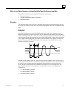
waveforms, C-5
Bus B LED, 2-2
Bus Controller version required, 1-9
Bus Interface Unit
I/O memory, 4-2
installing on terminal block, 3-14
introduction, 1-3
removing from terminal block, 3-14
Bus Redundancy, 1-11
configuring, 5-11
Bus switching, 1-11
Bus Switching Module, 1-12
C
Cable types, C-4
Cables
between terminal blocks, 2-8
installing, 3-8
Calibration datagram, 8-30
Channel Active
Analog input module, 5-30
Analog output module, 5-37
Analog Voltage Output module, 5-86
Grouped Analog Input module, 5-45, 5-53, 5-60,
5-95