


C-2 Field Control™ Genius® Bus Interface Unit User’s Manual
–
October 1999 GFK-0825F
C
Electrical Interface
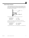
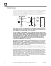
The Genius serial bus uses computer grade twisted pair data cable. The half duplex token sequence
used requires only a single pair since at any time only one station is transmitting and all others are
receiving. All stations must receive in order to track the present token value and take their
appropriate turn on the bus, regardless whether the data is to be used locally. The transmit sequence
is the same as the serial bus address (SBA) set into each location during configuration. A
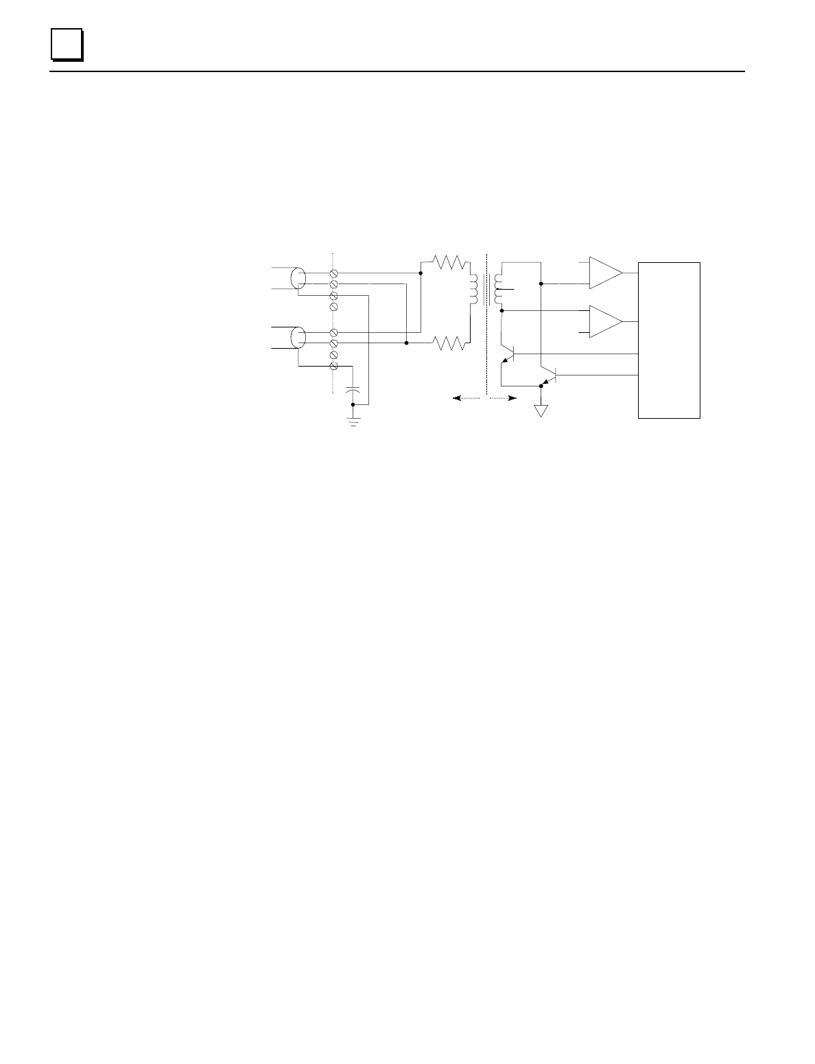
simplified interface circuit is shown below:
LOCAL
SUPPLY
CHASSIS
GROUND
COMP
COMP
R
R
RX+
RX-
TX+
TX-
INTERFACE
LOGIC
+ REF
- REF
LOCAL
COMMON
ISOLATION
SHIELD
IN
SHIELD
OUT
SER1
SER2
+5 to 10 V
SER1
SER2
SER2
Wiring Terminals
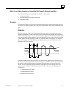
Signal coupling to the bus is via a high frequency, high isolation pulse transformer. This permits
the bus and the local logic to be at different voltage levels. The pulse waveforms are bipolar (see
next section below) to reduce DC baseline offsets in the waveform.
The daisy-chained bus is shown on the left in the above illustration. The SER 1 and SER 2 lines
are merely tapped at the intermediate locations along the bus. These connections must be consistent
since the signal is polarized. The shield of the cable is broken into segments at each location. Each
shield segment is DC grounded at one end (SHIELD OUT), and terminated with a small capacitor
at the other (SHIELD IN). The segmenting breaks up long ground loop paths. The capacitor
termination reduces common mode noise from high frequency pickup, while preventing large
ground loop currents in the shield at low frequencies.
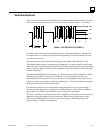
The alternately switching transistors produce a negative pulse followed by a positive pulse across
SER
IAL
1
relative to
SER
IAL
2
. The bit waveform is a series of these pulses, as will be shown
later. The transformer provides isolation (2500 volts test) between the bus and the local logic,
permitting these to be at different voltages. The internal resistors in each line provide current limit
and some termination function during transmission.
The balanced (differential) signals on the twisted pair provide high noise immunity due to the
magnetic (H field) cancellation effect of the twisting, as well as electric (E field) reduction by the
shielding. Most remaining noise pickup is common mode: the transformer provides a high common
mode noise rejection by looking only at the differential signal across the SER 1-2 lines. The two
input comparators detect the positive polarity input pulses separately from the negative; these are
sent to a custom interface logic chip which digitally filters these for timing and sequence, then
reconstructs the NRZ digital data. Voltages between the two thresholds are ignored. This filtering,
and the high input threshold if the comparators, are highly effective in rejecting both random
impulse noise and low level line reflections. Finally a CRC-6 checksum check is performed before
the data is sent to the local processor (not shown).