


GFK-0825F Chapter 7 Monitoring and Controlling Field Control Data 7-7
7
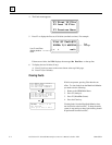
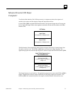
Monitor/Control I/O Data:
Computer
To utilize the Bus Interface Unit's I/O data correctly, a computer must know the sequence of
modules in the station, and the amount of input and output data each has.
For the PCIM, QBIM, and other GENI-based interfaces, the input and output data will occupy the
Device Input and Output Tables at the segments associated with the serial bus address of the Bus
Interface Unit.
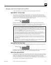
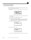
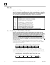
I/O Tables
Input Table
Output Table
32 segments, 128 bytes each
32 segments, 128 bytes each
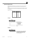
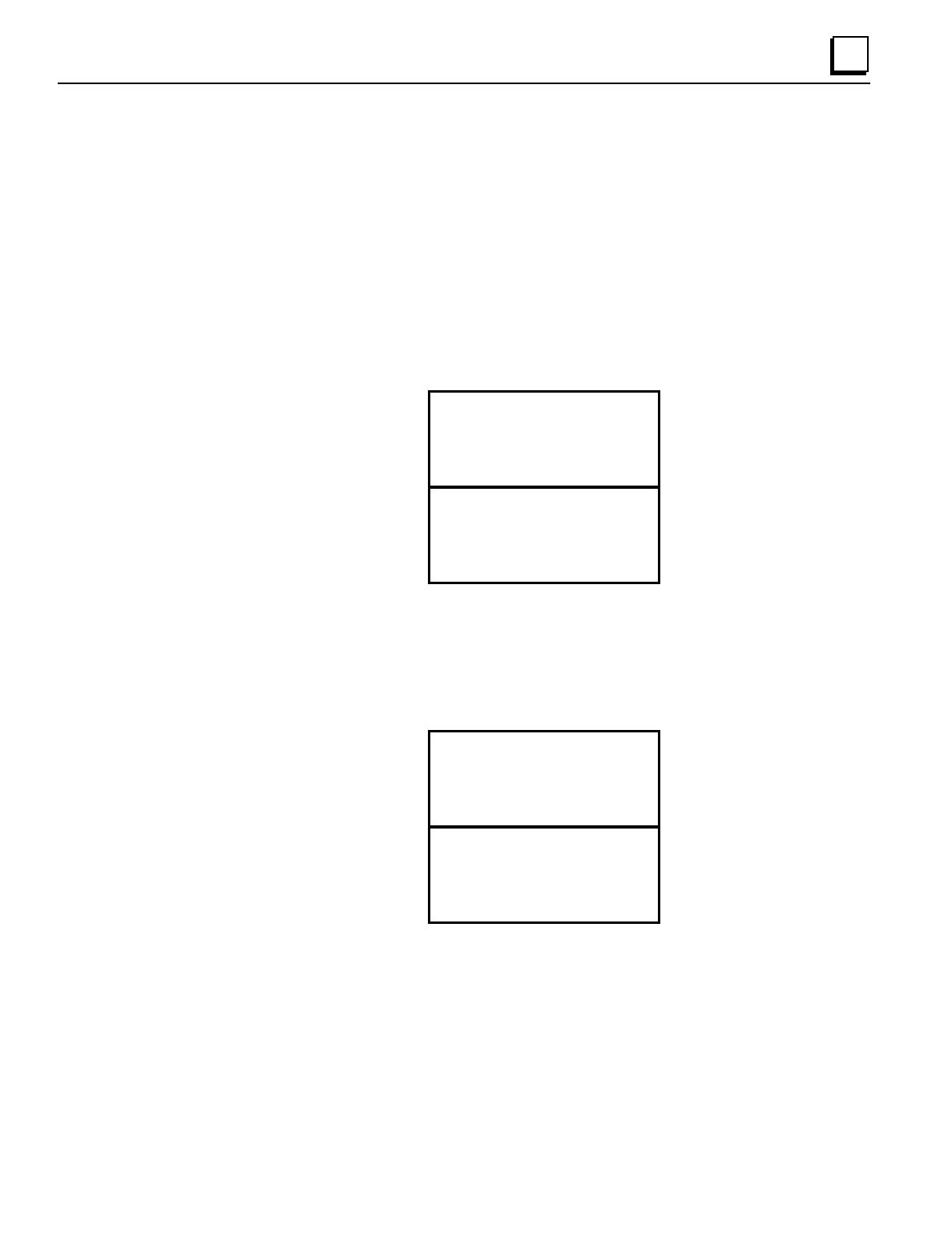
The Bus Interface Unit automatically sends all discrete inputs followed by all analog inputs from
the station, each bus scan. The PCIM or QBIM places this data into its Input Segment. The
application program must read the Input Segment to obtain the input data from the PCIM or QBIM.
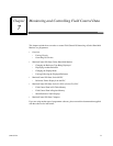
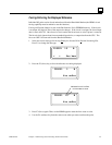
Input Table Segment for a
Bus Interface Unit
Discrete Inputs Bits
(number of bytes = configured
I length / 8)
Analog Input Words
(number of bytes = configured
AI length X 2)
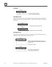
The Output Segment is used similarly. The application program must send to the PCIM or QBIM's
Output Segment all the discrete outputs followed by all the analog outputs for the station. The
PCIM or QBIM will automatically direct the outputs to the Bus Interface Unit each bus scan.