


5-12 Field Control™ Genius® Bus Interface Unit User’s Manual
–
October 1999 GFK-0825F
5
Configure CPU Redundancy
If the Bus Interface Unit will be used on the same bus with two controllers (PLCs or network
controller computers), and both of the controllers will send it outputs, the Bus Interface Unit must
be set up for CPU Redundancy. The two types of CPU Redundancy, Hot Standby and Duplex, are
defined below. If either type of redundancy is selected, the Bus Interface Unit will automatically
provide inputs and diagnostics to both of the redundant CPUs.
If the station contains any analog modules, the only form of CPU redundancy permitted is Hot
Standby. The Hand-held Monitor will permit selection of either type of CPU redundancy. Do not
select Duplex if there are any analog modules in the station.
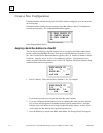
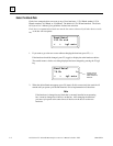
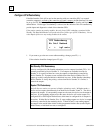
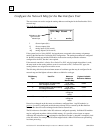
CPU Redundancy
No Cntl Redund
< > tgl entr
1. If you want to go to the next screen without making a change, press F2 ( > ).
If the selection should be changed, press F3 (tgl).
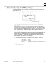
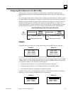
Hot Standby CPU Redundancy
A device configured for Hot Standby redundancy receives outputs from both CPUs. It is
normally controlled by Device Number 31. If no outputs are available from Device
Number 31 for a period of three bus scans, the outputs are immediately controlled by
Device Number 30. If outputs are not available from either Device Number 30 or 31,
outputs go to their configured default or hold their last state. In Hot Standby redundancy,
Device Number 31 always has priority, so that when Device Number 31 is on-line, it
controls the outputs.
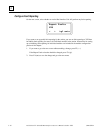
Duplex CPU Redundancy
Only all-discrete stations can operate in Duplex redundancy mode.
In Duplex mode, a
device receives outputs simultaneously from both Device Number 30 and 31. The device
compares the outputs. If corresponding outputs are the same, the device sets the output to
that state. If corresponding outputs are not the same, the device will set the output to its
configured ON or OFF Duplex Default State, which must be configured for all outputs in
the station. If either Device Number 30 or 31 stops sending outputs to a device, its outputs
are directly controlled by the remaining device. If both 30 and 31 stop sending outputs,
the outputs in the station either default to their programmed default state (not the Duplex
Default State), or hold their last state, as configured.