


GFK-0825F A-1
Scaling Analog Channels
This appendix explains how to select scaling values when configuring an analog input or output.
See chapter 5 for configuration instructions.
How Scaling Works
Analog modules convert between electrical signals (current or voltage) and digital values. These
digital values are 0 to 4095 (for 12-bit converters). Digital values are often referred to as “counts”
They represent the data that is transferred between the Bus Interface Unit and an analog module.
To make the input or output data of conventional analog modules more meaningful to the
application, the Bus Interface Unit performs a conversion process called scaling (note that the BIU
performs scaling only for conventional analog modules; “ntelligent” analog modules perform their
own scaling). Scaling converts the module's digital values to or from the engineering units values
used by the application.
Typically, the engineering units represent millivolts or microamps. In other cases, they represent
physical units such as degrees or centimeters per second. Since engineering units values are
integers from -32767 to +32767, it is often necessary to use fractional units (such as hundredths of
degrees) to preserve the resolution of a physical input or output.
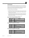
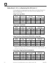
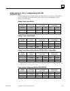
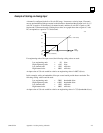
Each channel of an analog module can be scaled independently. Scaling is configured by entering
corresponding low and high engineering units values and low and high internal values for two
points. The internal values represent millivolts or microamps.
The BIU uses the straight line defined by the two pairs of values to convert between engineering
units and analog convertor counts. The conversion takes into account the module type and the
range that is selected.
A
Appendix