


GFK-0825F Chapter 8 Datagrams 8-23
8
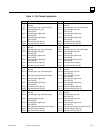
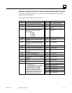
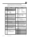
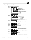
Additional Configuration Data for a Thermocouple Input Module
The content of configuration data bytes 14 to 187 for a Thermocouple module (IC670ALG630) is
listed below.
Byte Description Byte Description
14 Number of input reference parameters (2)
15 Number of output reference parameters (2)
16, 17 Byte length of analog input data
18, 19 Memory type for the module's analog input data,
usually type AI. Enter one of the following
numbers: 16 = I table
18 = Q table
10 = AI table
12 = AQ table
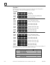
48, 49 Thermocouple type for input 1 (only used for
conversion types 1 & 2 (see bytes 46, 47)
0 = none 8 = N
1 = J 9 = G
2 = K 10 = C
3 = T 11 = D
4= E 12 = Platinel II
5 = S 13 = non-standard TC 1
6 = R 14 = non-standard TC 2
20, 21 Relative offset from start of table
22, 23 Byte length of discrete diagnostic input data
24, 25 Memory type for the module's diagnostic input bits,
usually type I. Enter one of the numbers listed
above.
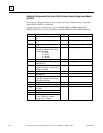
50, 51 Range type for input 1. This is used ONLY If range
type (see bytes 48, 49) is set to 0.
0 = unused 4 = 156 mV
1 = 19.5 mV 5 = 312.5 mV
2 = 39 mV 6 = 625 mV
3 = 78 mV
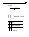
26, 27 Relative offset from start of table
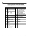
28, 29 Byte length of discrete control output data
30, 31 Memory type for the module's control output bits,
usually type Q. Enter one of the numbers listed
above.
52, 53 Remote Junction Compensation for input 1 :
0 = none
1 = use local thermistor
2 = use a value supplied in the module's
analog output (AQ) data
3 = use the configured value ( bytes 58, 59)
32, 33 Relative offset from start of table 54, 55 Low Alarm for input 1 (-32767 to +32767)
34, 35 Byte length of analog output data (for cold junction
compensation), usually type AQ
56, 57 High Alarm for input 1 (-32767 to +32767)
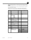
36, 37 Memory type for the module's analog output data
(used for remote junction compensation). Usually
type AQ. Enter one of the numbers listed above.
38, 39 Relative offset from start of table
58, 59 Remote Junction value for input 1. Used only if
Remote Junction Compensation (bytes 52, 53) is
3. The module multiplies this value by 100 then
adds it to the input voltage before performing
linearization. (-327.67 to +327.67).
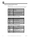
40, 41 Line Frequency (0 = 50 Hz, 1 = 60 Hz)
42, 43 Open circuit checking suppression for input 1 (0 =
perform check, 1 = suppress check)
60, 61 Offset for input 1. Used if conversion type (bytes
46, 47) is degrees C or F. This value should be in
the same units. The module multiplies the value by
100 before using it. Range is -100.00 to +100.00
degrees.
44, 45
Channel active for input 1 ( 0 = inactive, 1 = active)
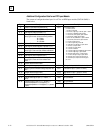
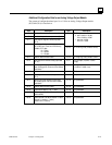
62 - 79 Ch 2 parameters
80 - 97 Ch 3 parameters
98-115 Ch 4 parameters
116-133 Ch 5 parameters
134-151 Ch 6 parameters
152- 169 Ch 7 parameters
46, 47 Conversion type for input 1:
0 = 1/100 millivolts
1 = linearized temperature in 1/10 degrees C
2 = linearized temperature in 1/10 degrees F
3 = percent of span (fractional format)
170- 187 Ch 8 parameters