


3-11
Cisco Intrusion Prevention System CLI Sensor Configuration Guide for IPS 7.1
OL-19892-01
Chapter 3 Initializing the Sensor
Advanced Setup
[3] Add/Modify Promiscuous Vlan Groups.
[4] Add/Modify Inline Interface Pairs.
[5] Add/Modify Inline Interface Pair Vlan Groups.
[6] Modify interface default-vlan.
Option:
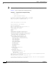
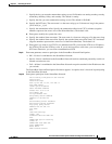
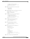
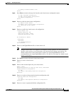
Step 15 Enter 4 to add an inline interface pair and see these options.
Available Interfaces
GigabitEthernet0/1
GigabitEthernet0/2
GigabitEthernet0/3
Step 16 Enter the pair name, description, and which interfaces you want to pair.
Pair name: newPair
Description[Created via setup by user asmith:
Interface1[]: GigabitEthernet0/1
Interface2[]: GigabitEthernet0/2
Pair name:
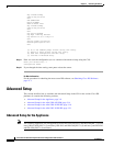
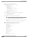
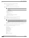
Step 17 Press Enter to return to the top-level interface editing menu.
[1] Remove interface configurations.
[2] Add/Modify Inline Vlan Pairs.
[3] Add/Modify Promiscuous Vlan Groups.
[4] Add/Modify Inline Interface Pairs.
[5] Add/Modify Inline Interface Pair Vlan Groups.
[6] Modify interface default-vlan.
Option:
Step 18 Press Enter to return to the top-level editing menu.
[1] Edit Interface Configuration
[2] Edit Virtual Sensor Configuration
[3] Display configuration
Option:
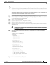
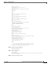
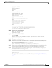
Step 19 Enter 2 to edit the virtual sensor configuration.
[1] Remove virtual sensor.
[2] Modify "vs0" virtual sensor configuration.
[3] Create new virtual sensor.
Option:
Step 20 Enter 2 to modify the virtual sensor configuration, vs0.
Virtual Sensor: vs0
Anomaly Detection: ad0
Event Action Rules: rules0
Signature Definitions: sig0
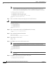
No Interfaces to remove.
Unassigned:
Promiscuous:
[1] GigabitEthernet0/3
[2] GigabitEthernet0/0
Inline Vlan Pair:
[3] GigabitEthernet0/0:1 (Vlans: 200, 300)
Inline Interface Pair:
[4] newPair (GigabitEthernet0/1, GigabitEthernet0/2)
Add Interface:
Step 21 Enter 3 to add inline VLAN pair GigabitEthernet0/0:1.