


5-32
Cisco Intrusion Prevention System CLI Sensor Configuration Guide for IPS 7.1
OL-19892-01
Chapter 5 Configuring Interfaces
Configuring VLAN Group Mode
Packets in the native VLAN of an 802.1q trunk do not normally have 802.1q encapsulation headers to
identify the VLAN number to which the packets belong. A default VLAN variable is associated with
each physical interface and you should set this variable to the VLAN number of the native VLAN or to 0.
The value 0 indicates that the native VLAN is either unknown or you do not care if it is specified. If the
default VLAN setting is 0, the following occurs:
• Any alerts triggered by packets without 802.1q encapsulation have a VLAN value of 0 reported in
the alert.
• Non-802.1q encapsulated traffic is associated with the unassigned VLAN group and it is not
possible to assign the native VLAN to any other VLAN group.
Note You can configure a port on a switch as either an access port or a trunk port. On an access port, all traffic
is in a single VLAN is called the access VLAN. On a trunk port, multiple VLANs can be carried over
the port, and each packet has a special header attached called the 802.1q header that contains the VLAN
ID. This header is commonly referred as the VLAN tag. However, a trunk port has a special VLAN called
the native VLAN. Packets in the native VLAN do not have the 802.1q headers attached.
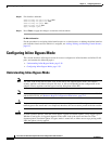
Deploying VLAN Groups
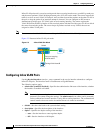
Because a VLAN group of an inline pair does not translate the VLAN ID, an inline paired interface must
exist between two switches to use VLAN groups on a logical interface. For an appliance, you can connect
the two pairs to the same switch, make them access ports, and then set the access VLANs for the two
ports differently. In this configuration, the sensor connects between two VLANs, because each of the
two ports is in access mode and carries only one VLAN. In this case the two ports must be in different
VLANs, and the sensor bridges the two VLANs, monitoring any traffic that flows between the two
VLANs.
You can also connect appliances between two switches. There are two variations. In the first variation,
the two ports are configured as access ports, so they carry a single VLAN. In this way, the sensor bridges
a single VLAN between the two switches.
In the second variation, the two ports are configured as trunk ports, so they can carry multiple VLANs.
In this configuration, the sensor bridges multiple VLANs between the two switches. Because multiple
VLANs are carried over the inline interface pair, the VLANs can be divided into groups and each group
can be assigned to a virtual sensor.
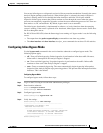
Configuring VLAN Groups
Note For information on what you need to configure if you are using the hardware bypass card on the IPS 4260
and the IPS 4270-20, see Hardware Bypass Configuration Restrictions, page 5-12.
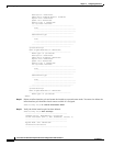
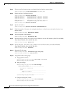
Use the physical-interfaces interface_name command in the service interface submode to configure
inline VLAN groups. The interface name is FastEthernet or GigabitEthernet.