


3-9
Cisco Intrusion Prevention System CLI Sensor Configuration Guide for IPS 7.1
OL-19892-01
Chapter 3 Initializing the Sensor
Advanced Setup
Note Adding new subinterfaces is a two-step process. You first organize the interfaces when you edit the
virtual sensor configuration. You then choose which interfaces and subinterfaces are assigned to which
virtual sensors.
The interfaces change according to the appliance model, but the prompts are the same for all models. To
continue with advanced setup for the appliance, follow these steps:
Step 1 Log in to the appliance using an account with administrator privileges.
Step 2 Enter the setup command. The System Configuration Dialog is displayed. Press Enter or the spacebar
to skip to the menu to access advanced setup.
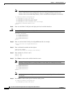
Step 3 Enter 3 to access advanced setup.
Step 4 Specify the Telnet server status. The default is disabled.
Step 5 Specify the SSHv1 fallback setting. The default is enabled.
Step 6 Specify the web server port. The web server port is the TCP port used by the web server (1 to 65535).
The default is 443.
Note The web server is configured to use TLS/SSL encryption by default. Setting the port to 80 does
not disable the encryption.
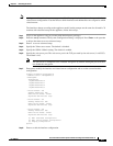
Step 7 Enter yes to modify the interface and virtual sensor configuration and to see the current interface
configuration.
Current interface configuration
Command control: Management0/0
Unassigned:
Promiscuous:
GigabitEthernet0/0
GigabitEthernet0/1
GigabitEthernet0/2
GigabitEthernet0/3
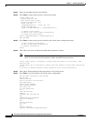
Virtual Sensor: vs0
Anomaly Detection: ad0
Event Action Rules: rules0
Signature Definitions: sig0
Virtual Sensor: vs1
Anomaly Detection: ad0
Event Action Rules: rules0
Signature Definitions: sig0
Virtual Sensor: vs2
Anomaly Detection: ad0
Event Action Rules: rules0
Signature Definitions: sig0
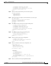
[1] Edit Interface Configuration
[2] Edit Virtual Sensor Configuration
[3] Display configuration
Option:
Step 8 Enter 1 to edit the interface configuration.