5-15
Cisco Intrusion Prevention System CLI Sensor Configuration Guide for IPS 7.1
OL-19892-01
Chapter 5 Configuring Interfaces
Configuring Physical Interfaces
For More Information
• For a list of supported sensor interfaces, see Interface Support, page 5-7.
• For more information on alternate TCP reset, see TCP Reset Interfaces, page 5-5.
• For more information on physical interfaces, see Configuring Physical Interfaces, page 5-15.
Interface Configuration Sequence
Follow these steps to configure interfaces on the sensor:
1. Configure the physical interface settings (speed, duplex, and so forth) and enable the interfaces.
2. Create or delete inline interfaces, inline VLAN subinterfaces, and VLAN groups, and set the inline
bypass mode.
3. Assign the physical, subinterfaces, and inline interfaces to the virtual sensor.
For More Information
• For the procedure for configuring the physical interface settings, see Configuring Physical
Interfaces, page 5-15.
• For the procedures for creating and deleting different kinds of interfaces, see Configuring Inline
Interface Mode, page 5-20, Configuring Inline VLAN Pair Mode, page 5-25, Configuring VLAN
Group Mode, page 5-31, and Configuring Inline Bypass Mode, page 5-38.
• For the procedure for configuring virtual sensors, see Adding, Editing, and Deleting Virtual Sensors,
page 6-5.
Configuring Physical Interfaces
Note For information on what you need to configure if you are using the hardware bypass card on the IPS 4260
and the IPS 4270-20, see Hardware Bypass Configuration Restrictions, page 5-12.
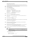
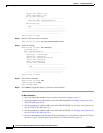
Use the physical-interfaces interface_name command in the service interface submode to configure
promiscuous interfaces. The interface name is FastEthernet, GigabitEthernet, or PortChannel.
Note You configure the ASA IPS modules (ASA 5500 AIP SSM, ASA 5500-X IPS SSP, and
ASA 5585-X IPS SSP) for promiscuous mode from the adaptive security appliance CLI and not from the
Cisco IPS CLI.
The following options apply:
• admin-state {enabled | disabled}—Specifies the administrative link state of the interface, whether
the interface is enabled or disabled.
Note On all backplane sensing interfaces on all modules, admin-state is set to enabled and is
protected (you cannot change the setting). The admin-state has no effect (and is protected)
on the command and control interface. It only affects sensing interfaces. The command and
control interface does not need to be enabled because it cannot be monitored.


