


14-26
Cisco Intrusion Prevention System CLI Sensor Configuration Guide for IPS 7.1
OL-19892-01
Chapter 14 Configuring Attack Response Controller for Blocking and Rate Limiting
Configuring Blocking and Rate Limiting Devices
You create and save Pre-Block and Post-Block VACLs in your switch configuration. These VACLs must
be extended IP VACLs, either named or numbered. See your switch documentation for more information
on creating VACLs. Enter the names of these VACLs that are already configured on your switch in the
Pre-Block VACL and Post-Block VACL fields.
The Pre-Block VACL is used mainly for permitting what you do not want the sensor to ever block. When
a packet is checked against the VACL, the first line that gets matched determines the action. If the first
line matched is a permit line from the Pre-Block VACL, the packet is permitted even though there may
be a deny line (from an automatic block) listed later in the VACL. The Pre-Block VACL can override the
deny lines resulting from the blocks.
The Post-Block VACL is best used for additional blocking or permitting that you want to occur on the
same VLAN. If you have an existing VACL on the VLAN that the sensor will manage, the existing VACL
can be used as a Post-Block VACL. If you do not have a Post-Block V ACL, the sensor inserts permit
ip any any at the end of the new VACL.
When the sensor starts up, it reads the contents of the two VACLs. It creates a third VACL with the
following entries:
• A permit line for the sensor IP address
• Copies of all configuration lines of the Pre-Block VACL
• A deny line for each address being blocked by the sensor
• Copies of all configuration lines of the Post-Block VACL
The sensor applies the new VACL to the VLAN that you designate.
Note When the new VACL is applied to a VLAN of the switch, it removes the application of any other VACL
to that VLAN.
For More Information
For the procedure for configuring blocking using router ACLs, see Configuring Blocking and Rate
Limiting Devices, page 14-21.
Configuring the Sensor to Manage Catalyst 6500 Series Switches and Cisco 7600 Series Routers
To configure the sensor to manage Catalyst 6500 series switches and Cisco 7600 series routers, follow
these steps:
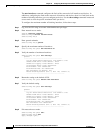
Step 1 Log in to the CLI using an account with administrator privileges.
Step 2 Enter network access submode.
sensor# configure terminal
sensor(config)# service network-access
sensor(config-net)#
Step 3 Specify the IP address for the router controlled by the ARC.
sensor(config-net)# cat6k-devices ip_address
Step 4 Enter the user profile name that you created when you configured the user profile. The ARC accepts
anything you type. It does not accept it, check to see if the logical device exists.
sensor(config-net-cat)# profile-name user_profile_name