


17-51
Cisco Intrusion Prevention System CLI Sensor Configuration Guide for IPS 7.1
OL-19892-01
Chapter 17 Administrative Tasks for the Sensor
Tracing the Route of an IP Packet
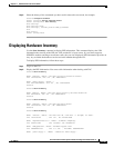
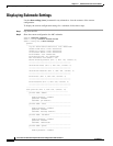
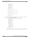
PID: IPS-4360 , VID: V01 , SN: FGL162740J6
Name: "RegexAccelerator/0", DESCR: "LCPX8640 (humphrey)"
PID: FCH162077NK , VID: 33554537, SN: LXXXXXYYYY
Name: "power supply 1", DESCR: "IPS4360 AC Power Supply "
PID: IPS-4360-PWR-AC , VID: 0700A, SN: 25Y1Y8
Name: "power supply 2", DESCR: "IPS4360 AC Power Supply "
PID: IPS-4360-PWR-AC , VID: 0700A, SN: 25Y1Y9
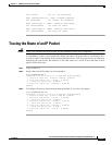
Tracing the Route of an IP Packet
Caution There is no command interrupt available for this command. It must run to completion.
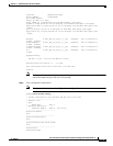
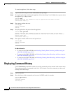
Use the trace ip_address count command to display the route an IP packet takes to a destination. The
ip_address option is the address of the system to trace the route to. The count option lets you define how
many hops you want to take. The default is 4. The valid values are 1 to 256. To trace the route of an IP
packet, follow these steps:
Step 1 Log in to the CLI.
Step 2 Display the route of IP packet you are interested in.
sensor# trace 10.0.0.1
traceroute to 10.0.0.1 (10.0.0.1), 4 hops max, 40 byte packets
1 192.0.2.2 (192.0.2.2) 0.267 ms 0.262 ms 0.236 ms
2 192.0.2.12 (192.0.2.12) 0.24 ms * 0.399 ms
3 * 192.0.2.12 (192.0.2.12) 0.424 ms *
4 192.0.2.12 (192.0.2.12) 0.408 ms * 0.406 ms
sensor#
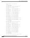
Step 3 To configure the route to take more hops than the default of 4, use the count option.
sensor# trace 10.0.0.1 8
traceroute to 10.0.0.1 (10.0.0.1), 8 hops max, 40 byte packets
1 192.0.2.2 (192.0.2.2) 0.35 ms 0.261 ms 0.238 ms
2 192.0.2.12 (192.0.2.12) 0.36 ms * 0.344 ms
3 * 192.0.2.12 (192.0.2.12) 0.465 ms *
4 192.0.2.12 (192.0.2.12) 0.319 ms * 0.442 ms
5 * 192.0.2.12 (192.0.2.12) 0.304 ms *
6 192.0.2.12 (192.0.2.12) 0.527 ms * 0.402 ms
7 * 192.0.2.12 (192.0.2.12) 0.39 ms *
8 192.0.2.12 (192.0.2.12) 0.37 ms * 0.486 ms
sensor#