


18-4
Cisco Intrusion Prevention System CLI Sensor Configuration Guide for IPS 7.1
OL-19892-01
Chapter 18 Configuring the ASA 5500 AIP SSM
Creating Virtual Sensors for the ASA 5500 AIP SSM
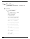
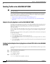
Software version: 7.0(1)E3
MAC Address Range: 0012.d948.fe73 to 0012.d948.fe73
App. name: IPS
App. Status: Up
App. Status Desc:
App. version: 6.2(1)E3
Data plane Status: Up
Status: Up
Mgmt IP addr: 171.69.36.171
Mgmt web ports: 443
Mgmt TLS enabled: true
asa#
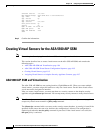
Step 3 Confirm the information.
Creating Virtual Sensors for the ASA 5500 AIP SSM
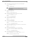
Note Cisco Adaptive Security Appliance Software 7.2.3 or later supports virtualization.
This section describes how to create virtual sensors on the ASA 5500 AIP SSM, and contains the
following topics:
• ASA 5500 AIP SSM and Virtualization, page 18-4
• ASA 5500 AIP SSM Virtual Sensor Configuration Sequence, page 18-5
• Creating Virtual Sensors, page 18-5
• Assigning Virtual Sensors to Adaptive Security Appliance Contexts, page 18-7
ASA 5500 AIP SSM and Virtualization
The ASA 5500 AIP SSM has one sensing interface, GigabitEthernet 0/1. When you create multiple
virtual sensors, you must assign this interface to only one virtual sensor. For the other virtual sensors
you do not need to designate an interface.
After you create virtual sensors, you must map them to a security context on the adaptive security
appliance using the allocate-ips command. You can map many security contexts to many virtual sensors.
Note The allocate-ips command does not apply to single mode. In this mode, the adaptive security appliance
accepts any virtual sensor named in a policy-map command.
The allocate-ips command adds a new entry to the security context database. A warning is issued if the
specified virtual sensor does not exist; however, the configuration is allowed. The configuration is
checked again when the service-policy command is processed. If the virtual sensor is not valid, the
fail-open policy is enforced.