


64 | Control Panels, Control Centers, and Keypads | NZ 300
•
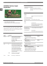
The NZ 300 LSN is equipped with an event database for
the last 1024 events. All alarms, malfunctions,
deactivations and control panel resets are stored. The
events, which are saved together with the date and
time, can be shown on the display of the BE 300 LSN or
using a PC. In addition, a print-out can be produced via
a PC.
Certifications and Approvals
Region Certification
Europe CE NZ 300 LSN
Germany VdS-S S 188709, A NMZ 300 A
S 184507, B NMZ 300 H
S 196602, B NMZ 1000 B
S 196001, C NMZ 1000 C
VdS G 100070, C NZ 300 LSN
G 101806, A AWUG-NZ 300
G 105079, C Zentralenumschrank
NZ300/NZ500
Installation/Configuration Notes
Energy balance
The energy balance is determined according to VDE 0833
and created using the "uezpro" planning and current
calculation program. The limits of the NZ 300 LSN are
automatically calculated and displayed.
The integrated power supply can be used to charge
batteries with a capacity of up to 34 Ah. The max. power
supply unit current (battery current + standby current) is
2.4 A. The bridging time is max. 60 hours.
For additional remote power supply, the NEV 300 LSN
power supply can also be used.
LSN planning
Applications/requirements NZ 300 LSN
Allocation of loops and stub lines. 1 x loop or max. 2 x stubs possible.
Using loop lines is recommended be-
cause loop lines provide greater se-
curity than stub lines.
Combining LSN expansion modules
and LSN detectors.
It is possible to combine LSN expan-
sion modules and LSN detectors on a
loop or stub line.
Combining automatic and non-auto-
matic
LSN detectors.
Combining automatic and non-auto-
matic LSN detectors is possible.
Connecting
conventional detectors.
To connect conventional emergency
call detectors, use the NNK 100 LSN
expansion module and 4 DC primary
lines, or the KD 55-1 LSN with 2 pri-
mary lines.
Power supply +V/0 V When calculating the cable length +V/
0 V of the NNK 100 LSN and
NVK 100 LSN expansion modules, it
is important to note that LSN expan-
sion modules require a minimum pow-
er supply of 9 V.
Connecting
LSN elements (E)
1.
Max. 127 LSN elements
(depending on current requirement).
Input addresses
2.
Max. 140
Output addresses
3.
Max. 64
Permissible current Max. 100 mA LSN line voltage
Length of line Max. 1000 m for loops
Max. 1000 m for stubs in total
1. LSN elements (E) are LSN expansion modules, LSN
detectors etc.
2. Input addresses for detectors, expansion modules,
activation
units etc.
3. Output addresses of e.g. LEDs.
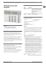
Arming devices
The following arming devices can be deployed in
conjunction with the NZ 300 LSN: SmartKey, block-type
lock, key switch (only contact key switches), BE 300 LSN
(user code).
The block-type lock must be connected using the
NVK 100 LSN expansion module. The key switch can be
connected at any expansion module input. The key switch
should be positioned in the vicinity of a BE 300 LSN, in order
to ensure that the activation/deactivation process can be
monitored.
The SmartKey key administration is performed at the
control panel via NzPara with max. 40 SmartKey keys.
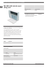
Parts Included
Type Qty. Component
NZ 300 LSN 1 Case and connection circuit board with in-
tegrated dialing modem (AWUG) and power
supply unit
Technical Specifications
Approval for telecommunications de-
vice
CE 0682
Housing
•
Dimensions (H x W x D)
460 x 380 x 97 mm
•
Color
Light gray/RAL 7035
•
Weight (excl. batteries)
2 kg
•
Weight (incl. batteries)
15 kg
Bosch Security Systems B.V. www.boschsecurity.com
1